JoaMat
-
Posts
1,466 -
Joined
-
Last visited
-
Days Won
16
Content Type
Profiles
Forums
Events
Everything posted by JoaMat
-
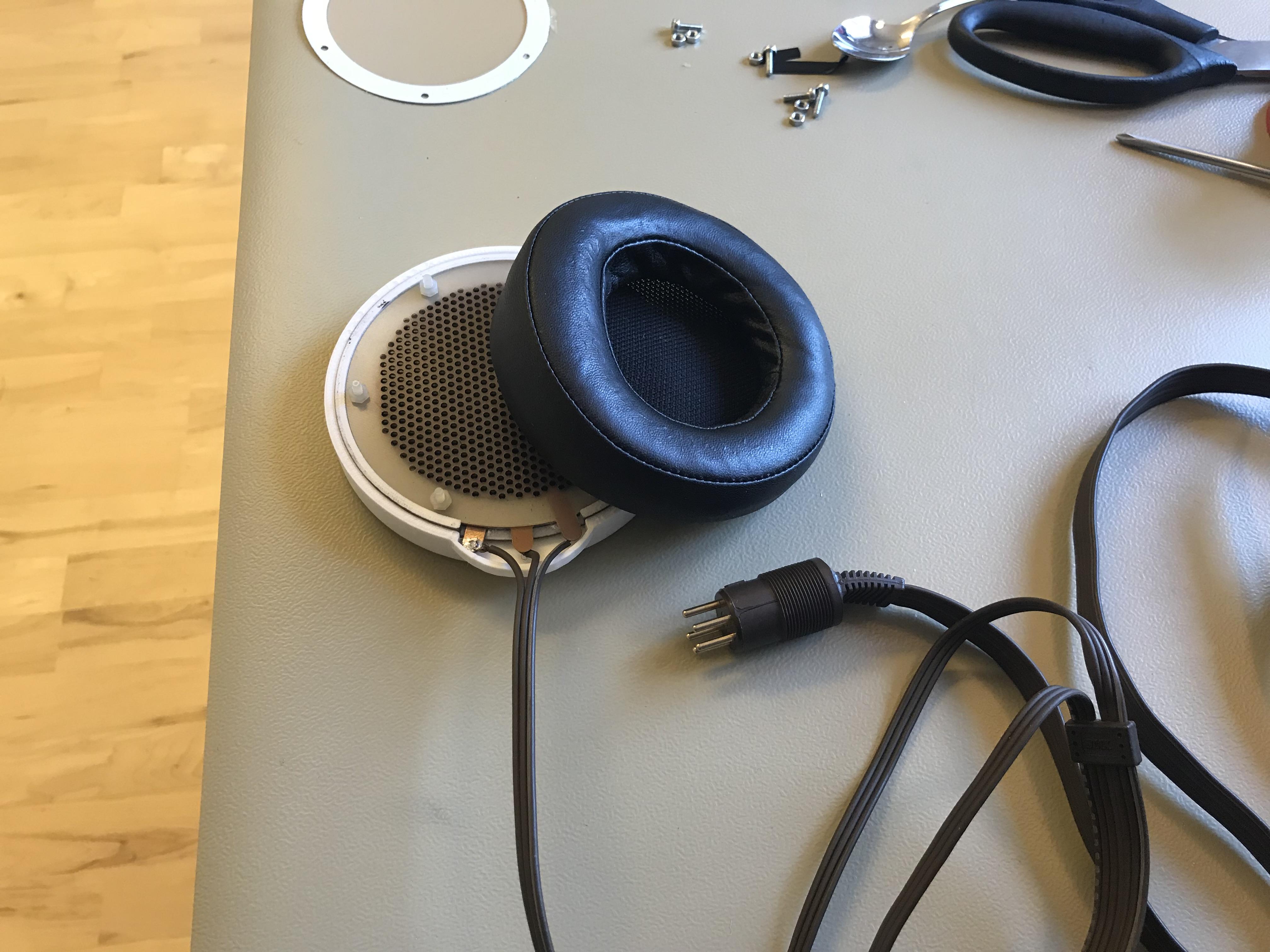
Listened to this for the first time today. Pad is from a SR-007 and cable from an old Lambda and the rest is home made. The main parts are made with files from Wachara (chinsettawong). Many thanks. A lot more has to be done before it’s a decent headphone.

-
https://en.wikipedia.org/wiki/Aluminium_oxide
-
Normal or not – I don’t know. You apply LV cross the current course? This is an old post of mine when I checked current sources of a Carbon. I still don't understand....
-
Wow, I like that Scanivox box – beautiful.
-
We have to keep this thread alive, don’t we. New version of 4093 based timer for T2 PSU - replaces the 555 IC. Makes a LED flashing during pre-heat and get steady when high voltages kicks in. Old to the left and new to the right. New in place in the T2 power supply.
-
Did this today. Dual headphone connectors. Not my amplifier.
-
Lovely to see a KGSShv with on board heat sinks again!
-
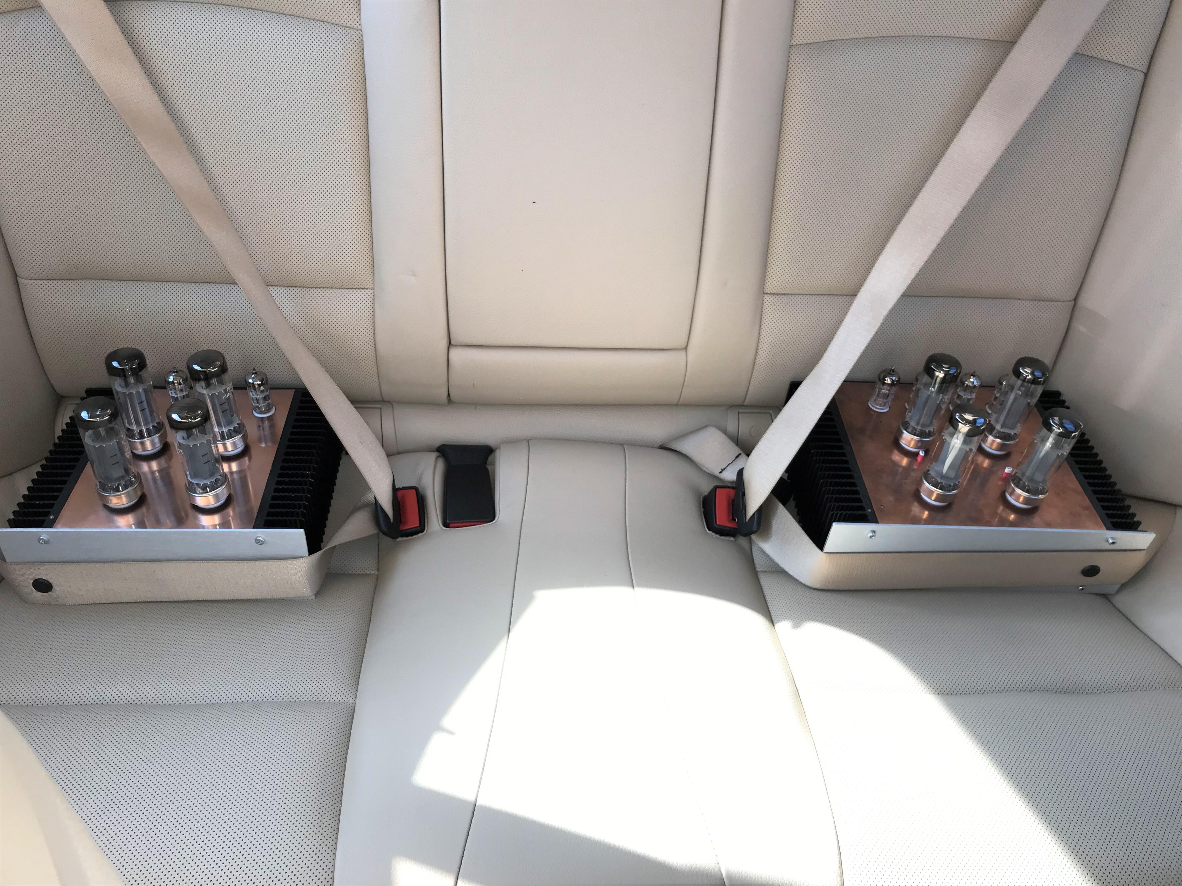
I took these two fellows.. …on a ride to big brother who has his own original Kevin DIY T2 PSU (reduced voltages - everything else as original). With this PSU both mini T2 are silent - no annoying hum. Here they are all together.
-
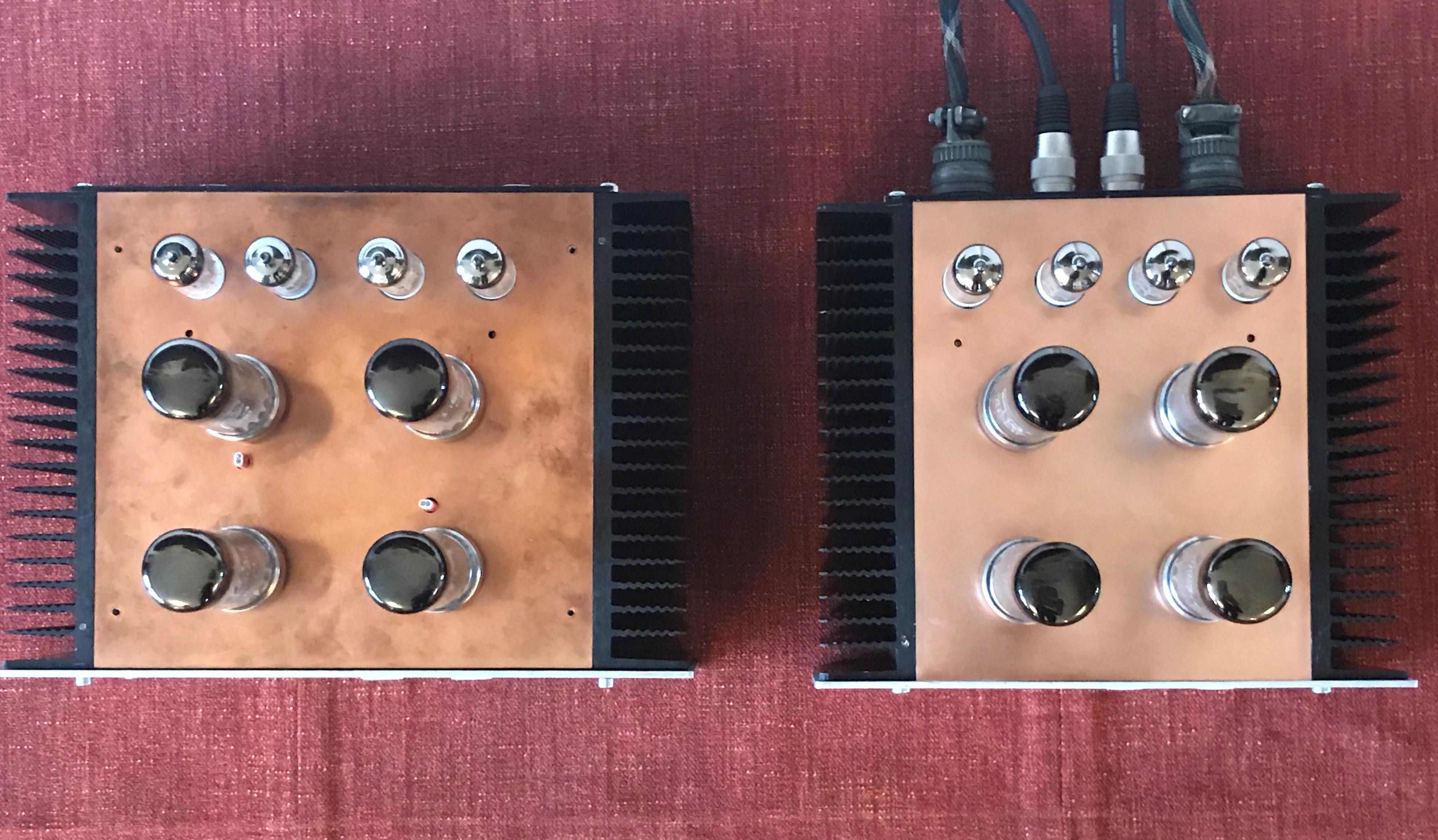
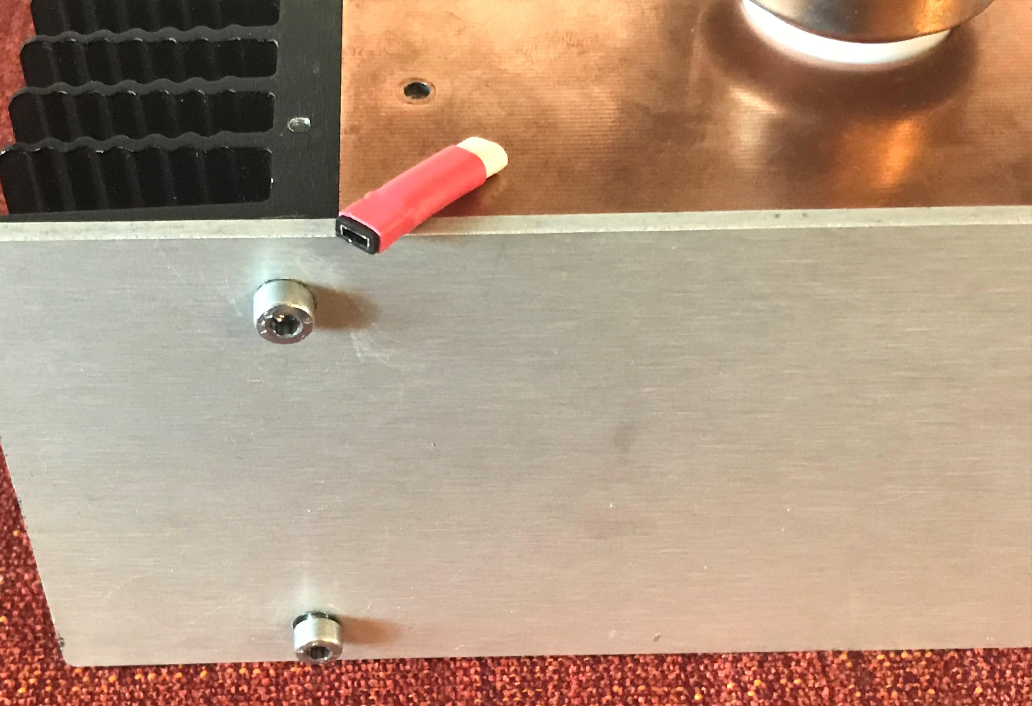
Thanks folks. Aerial picture of old and new “mini T2”. The new just got a top plate, looks rather nice when newly polished. Small holes in front of small tubes are for trimmers. I drilled two 6.5mm holes in the old to plate (between big tubes) for the balance servo jumpers. Made this jumper with a piece of cable and heat shrink.
-
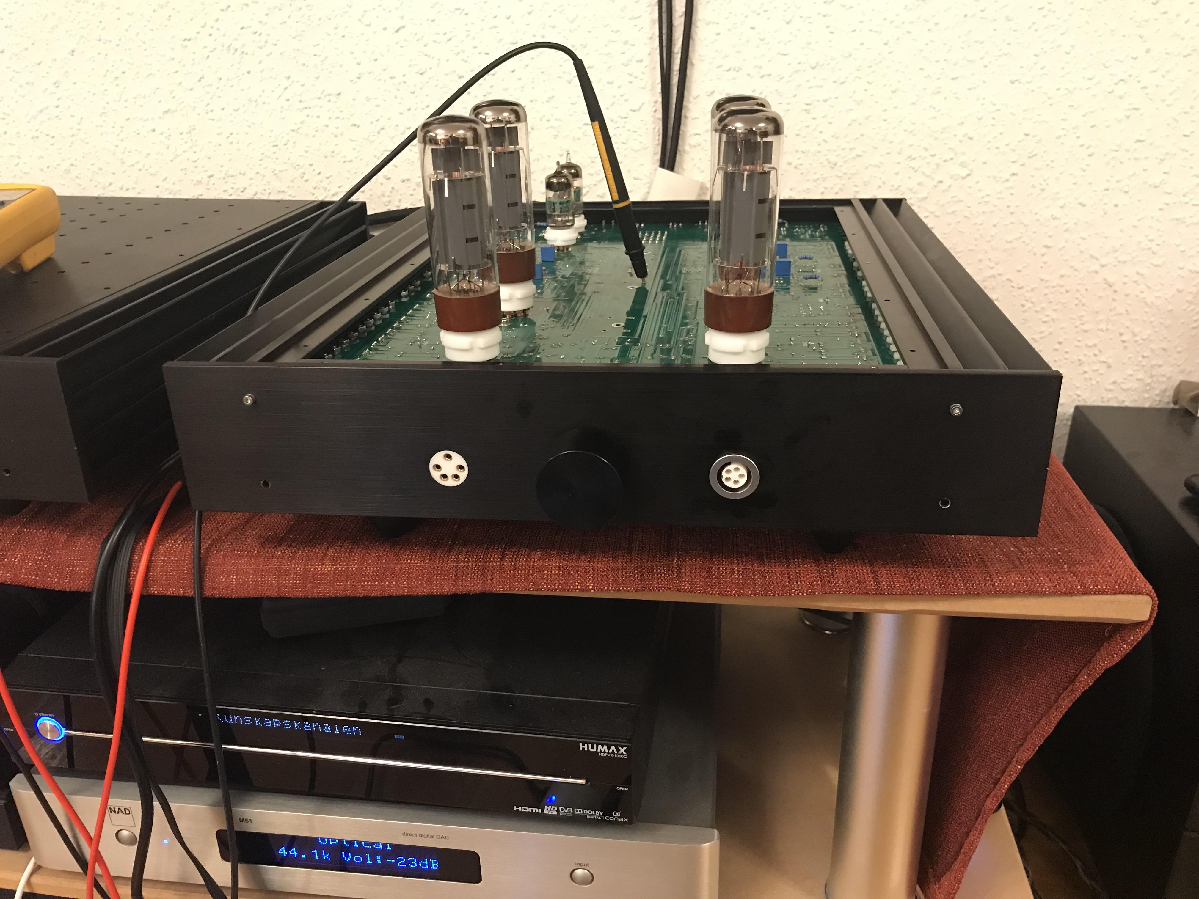
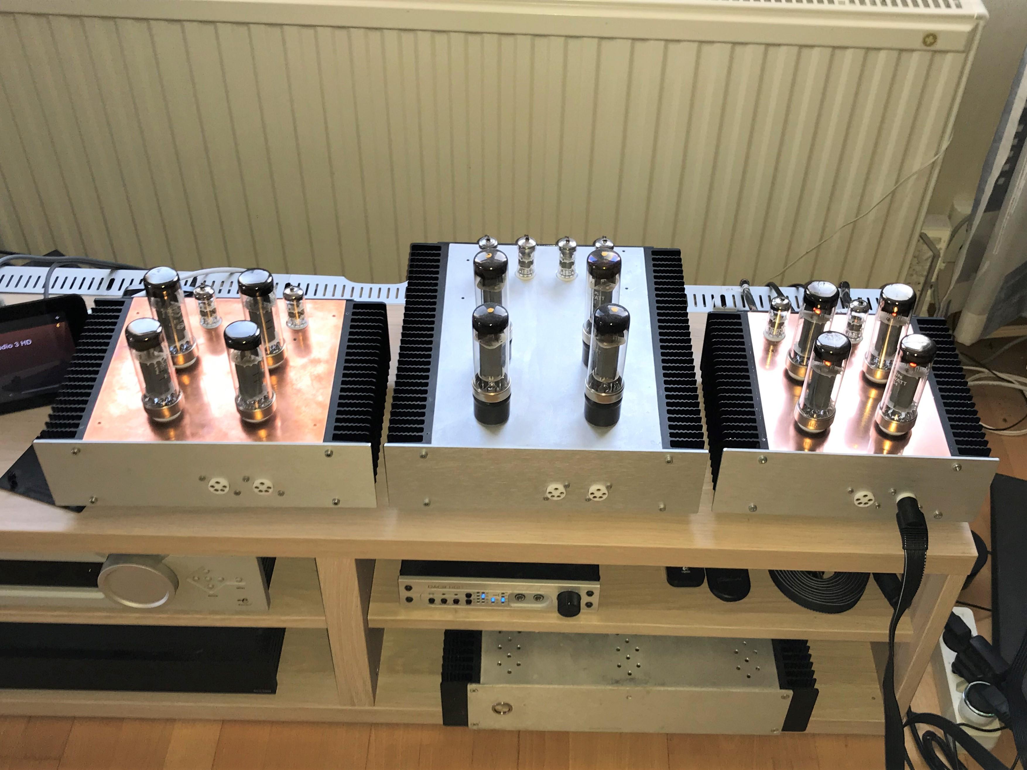
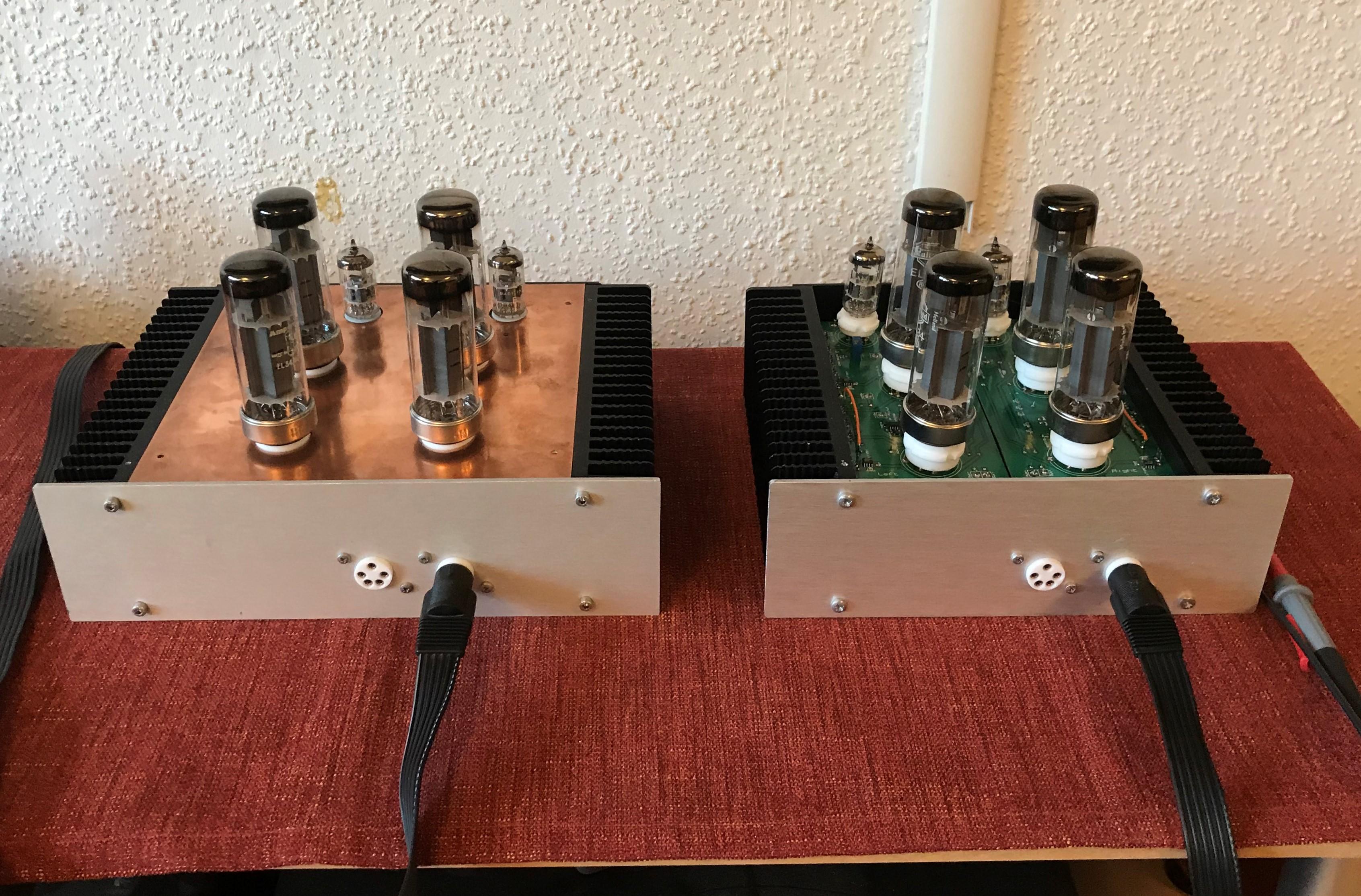
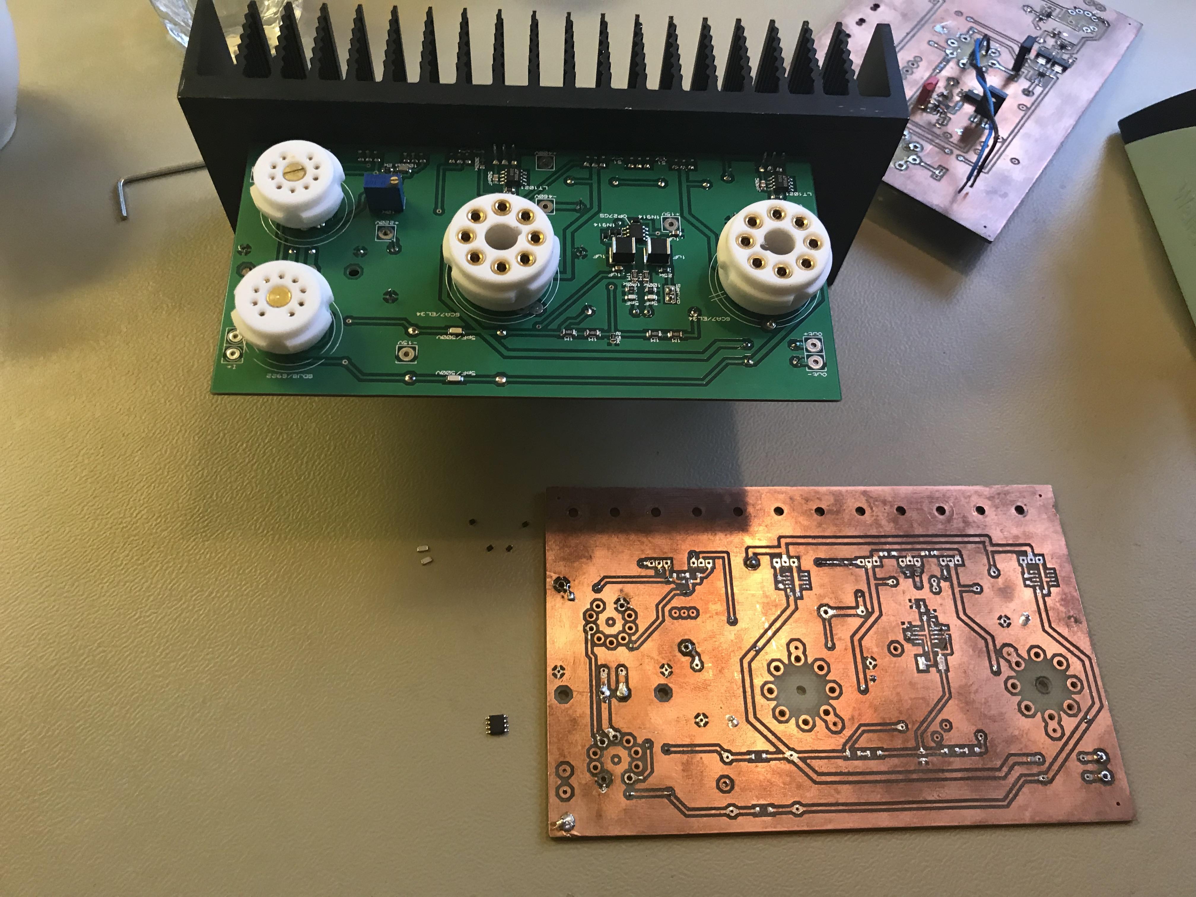
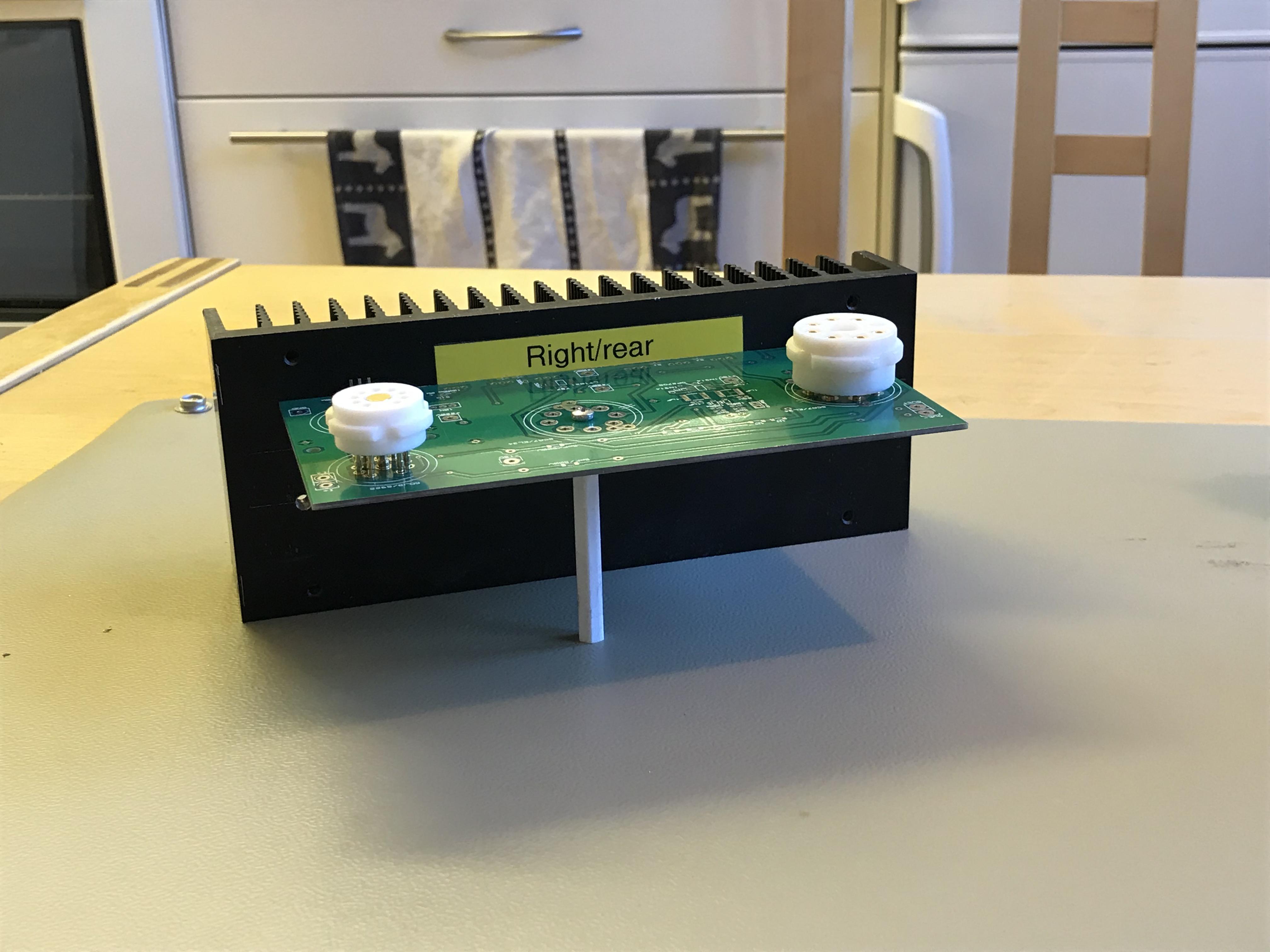
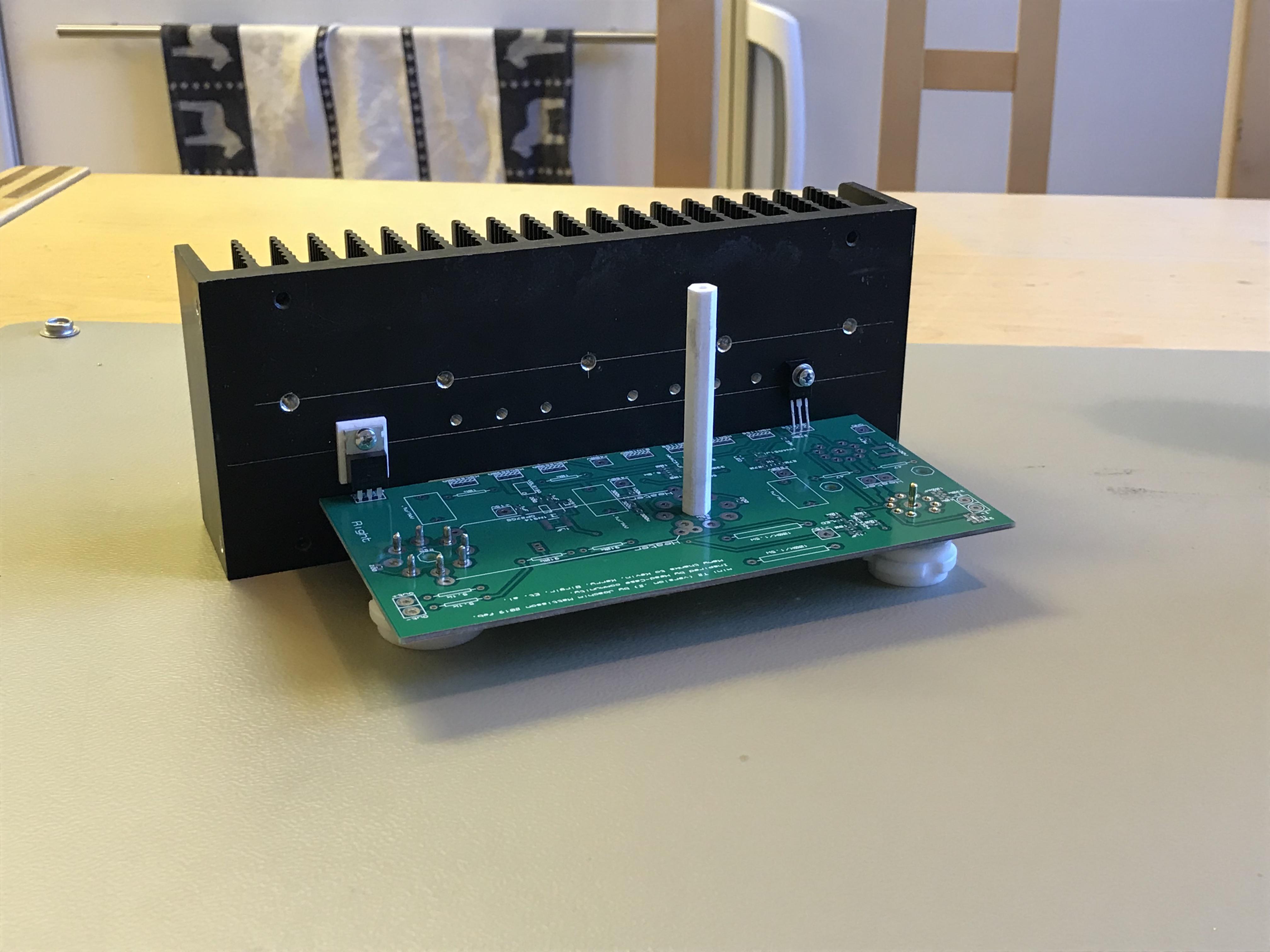
To the right is a just finished mini T2. Transistors mounted direct onto heat sinks. Inner width is 159 mm (6.26 in). Most of the components are moved from my first amplifier with in kitchen made boards, including the small LEDs and diodes. Heat sinks, all connectors (STAX, Neutrik, Amphenol) are from one of my full size DIY T2 (RIP – I’ll build a new one with all original parts) This is my third mini T2. The building process has been straight forward. The only thing is that left channels of all the three amplifiers have a bloody annoying hum during the first minutes after start up. I’ve no idea what causes it.
-
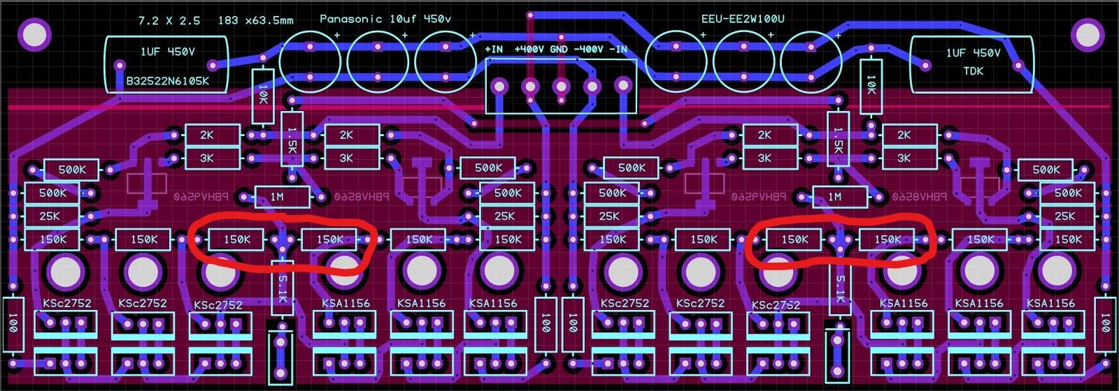
Shorted out the 150K resistors in red circles which then bypasses corresponding Darlington pairs. I run amplifier +/-400 V and 5 mA. IMO the amplifier sounds about the same as with higher currents and all transistors on duty. I believe it’s possible to build a decent all SMD version of the CFAE. Reduce voltage to let say +/-300 V - how small can one build a power supply?
-
Now when there are nice tapping tools out there I think I try mount sands direct on heat sink. I've done this today. I cut of 20 mm of the board where the bracket should be so now it’s 80 mm x 160 mm. The layout was not meant for this so there is a need for a couple of extra jumper wires. Most things are doable. Here is my tapping tool with rather long shaft M3 tap.
-
There are three wire jumpers on each boards. Two for big tubes filament so two good wires between the tubes. Then there is a small jumper along one side of OP27 (see silk screen component side (which one now that is…)), easy to forget - I use a piece of a wire from power resistor. It connects -15V to the balance opamp.
-
Two sets, please. Thanks for doing this Michael.
-
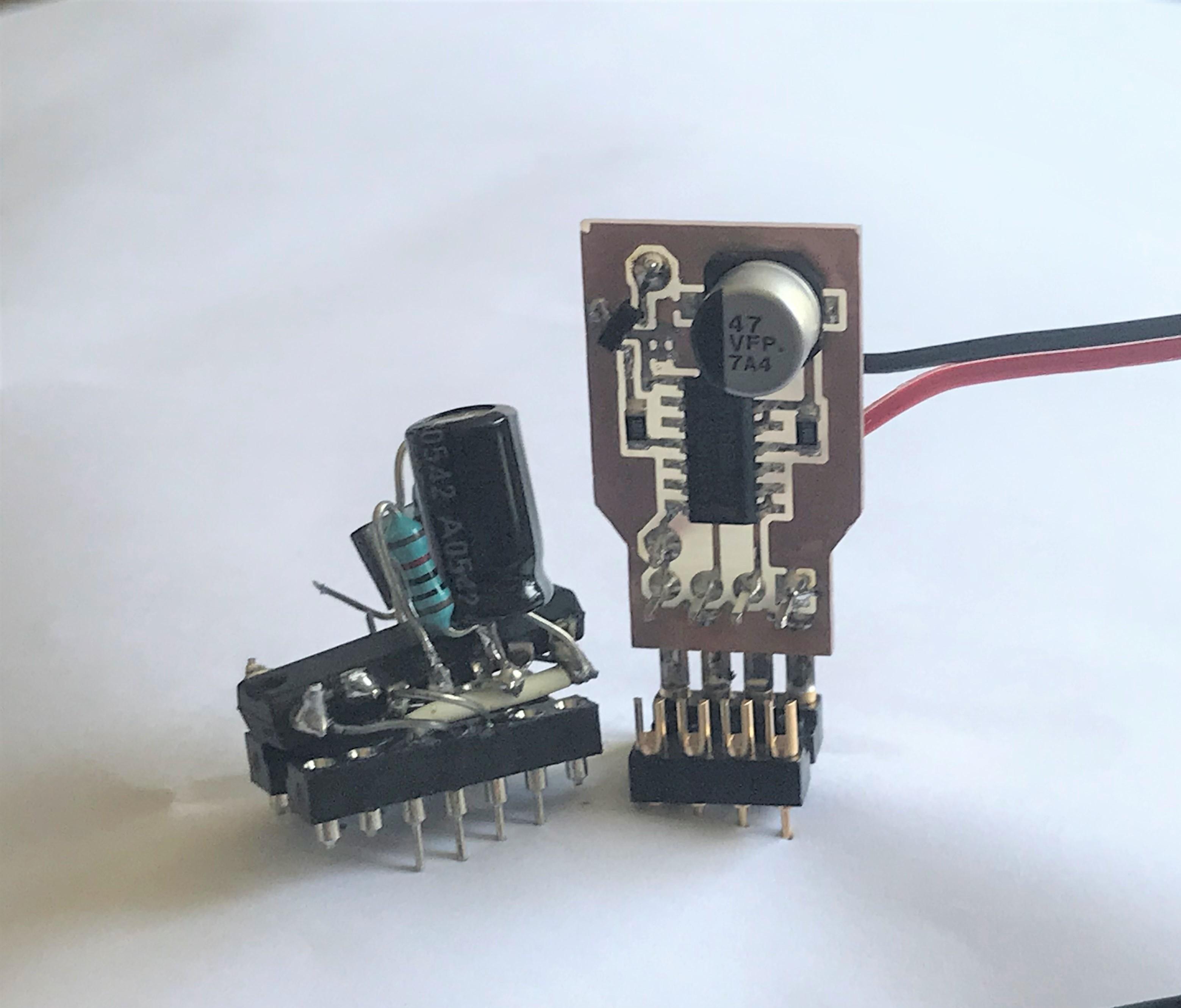
LT1021-7 is worth trying – in LTspice it acts like LT1021-10 and LT1236-10. The LED TLMS1100 is a tiny thing and personally I think that’s the most tricky part to handle and solder. I started to use it in battery daughter board for T2 and I did buy a hundred pieces right away. It might be a good idea to buy some extra in case if you lose one (on floor, overheat when solder or what so ever). Now days I solder in the LED first and then check it with DMM in diode test mode, positive test pin on anode and negative on cathode and the LED will glow if everything is right (no guarantee for bad soldering though - by own experience). It will not glow with transistor and resistors in place. We send the designer a bottle of Scotch each and see what happens…
-
As DIYer you are entitled to do whatever you like. IMO 18 mA is at the higher end. For the moment I run mine at one fourth of 18 mA. I’ve my house full of heat sinks but that’s not a reason for high currents.
-
It looks like the LT1021 is abandoned by most supplier. Mouser is out of stock but claims that it’s on order. There is another 10 volt reference LT1236-10 that I think should be a good alternative. I’ve tested it in LTspice model by Kerry (jump here for reference and more info) and it seems to do the same as LT1021-10 but with 0.2 mA lower current with same current set resistor. Someone has to verify LT1236 works. I guess Kerry needs a couple of LTxxxx in above PSU.
-
Well, I rather not make recommendations but I would go for +400V/-460V and add one 20K/3W resistor on each board between +220V and +400V pads. I think I want something like this… ...for power supply.
-
I haven’t run the amplifier with 20K resistors for more than a day. But after switching power on and off frequently I do think this will work. With R1 and R3 at 270 ohm I get 9.0 to 9.1 mA at +220V (each board) and with PSU positive rail set to 400 V a 20K/3W resistor seems to fit perfect. I think gepardcv idea will work and in my opinion it’s absolutely worth trying. Current demand positive rail is approximately 80 mA and negative is 60mA. My earlier statement that a +220 V supply is preferred might be a bit exaggerated.
-
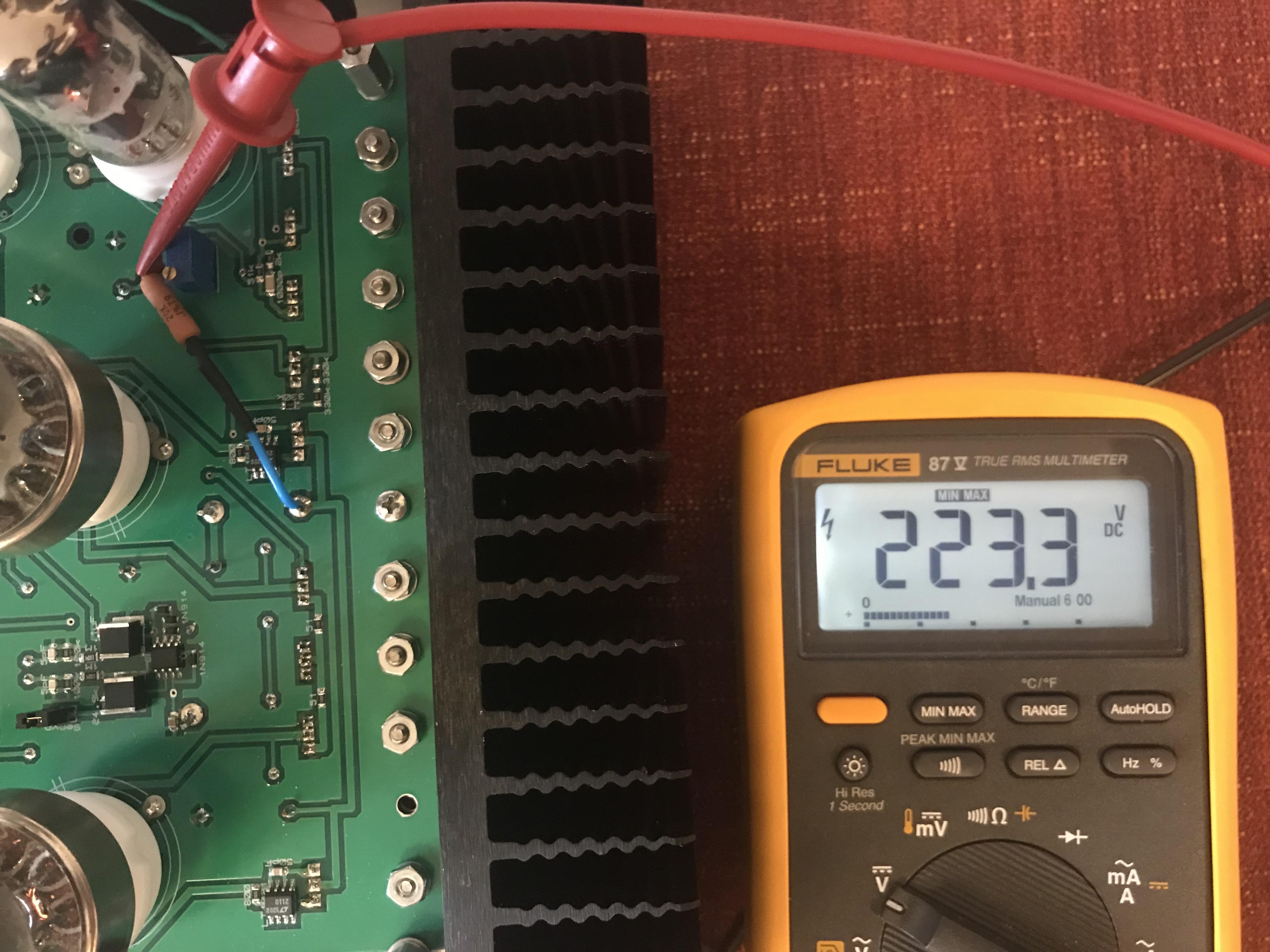
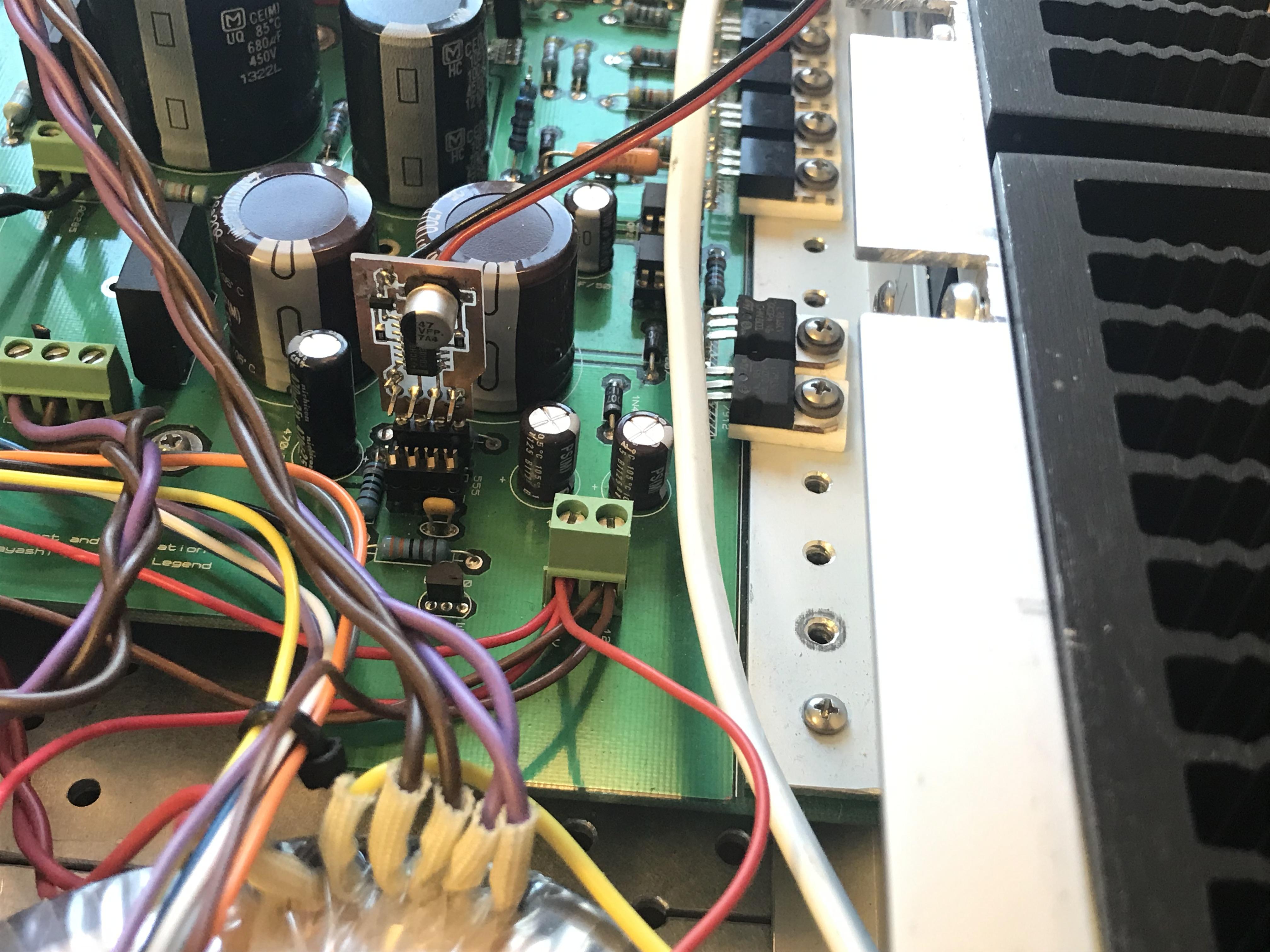
Back from skiing. Zoom in on the Vishay CPF3 resistor and you can read 20K. 400 volts in at the blue wire. The meter is in Min Max mode and it went up to 225.5 V at start up and then immediately down to what you see in Picture. Seems to work. I’ll change the other channel and will test this for some time. I have run the amplifier on a unchanged T2 PSU with +/-500 V and +250 V for a while and that also seems to work alright. Edit: Both channels now with 20K resistors to achieve the +220V. 220.3V respective 219.6V with PSU +400V trimmed to 401.9V on the clocks.
-
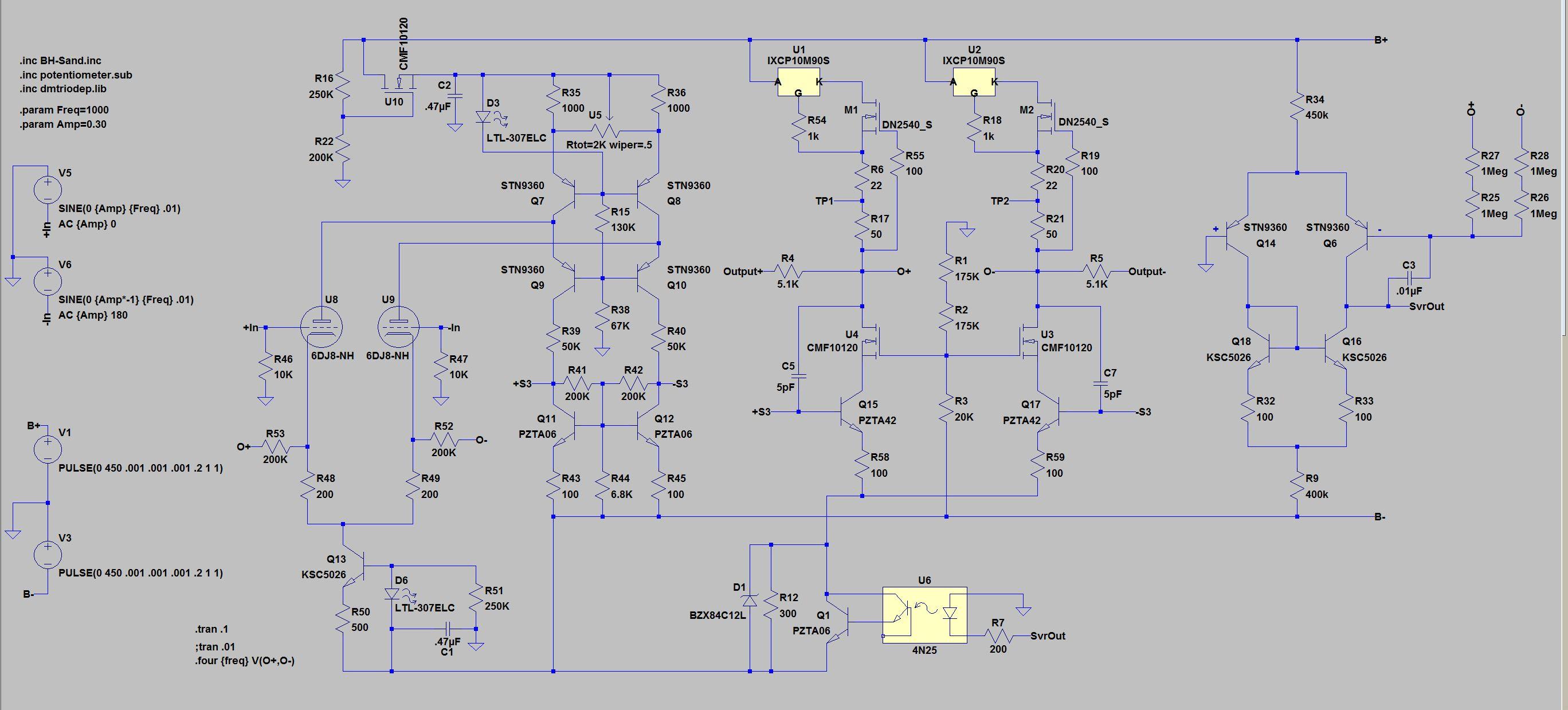
Maybe it’s not wise to entirely rely on a single 20K resistor. A better way probably is to use Zener diodes to achieve 220V as Kevin does with the KGSSHV-Tube-Sandwich. Another way could be using mosfet like Kerry did in below LTspice simulation – see U10, R16 and R22. Ref. Kerry post https://www.head-case.org/forums/topic/12949-stax-t8000-clone-well-sorta/?do=findComment&comment=764504
-
With R1 and R3 at 270R you get 4 mA through each current source plus 0.5 mA LED current. Put a resistor of 20K/2W between +400V and +220V pad on the amplifier board - gives approximately 224V. Someone try this and give a report? I’m on a Ski holiday.
-
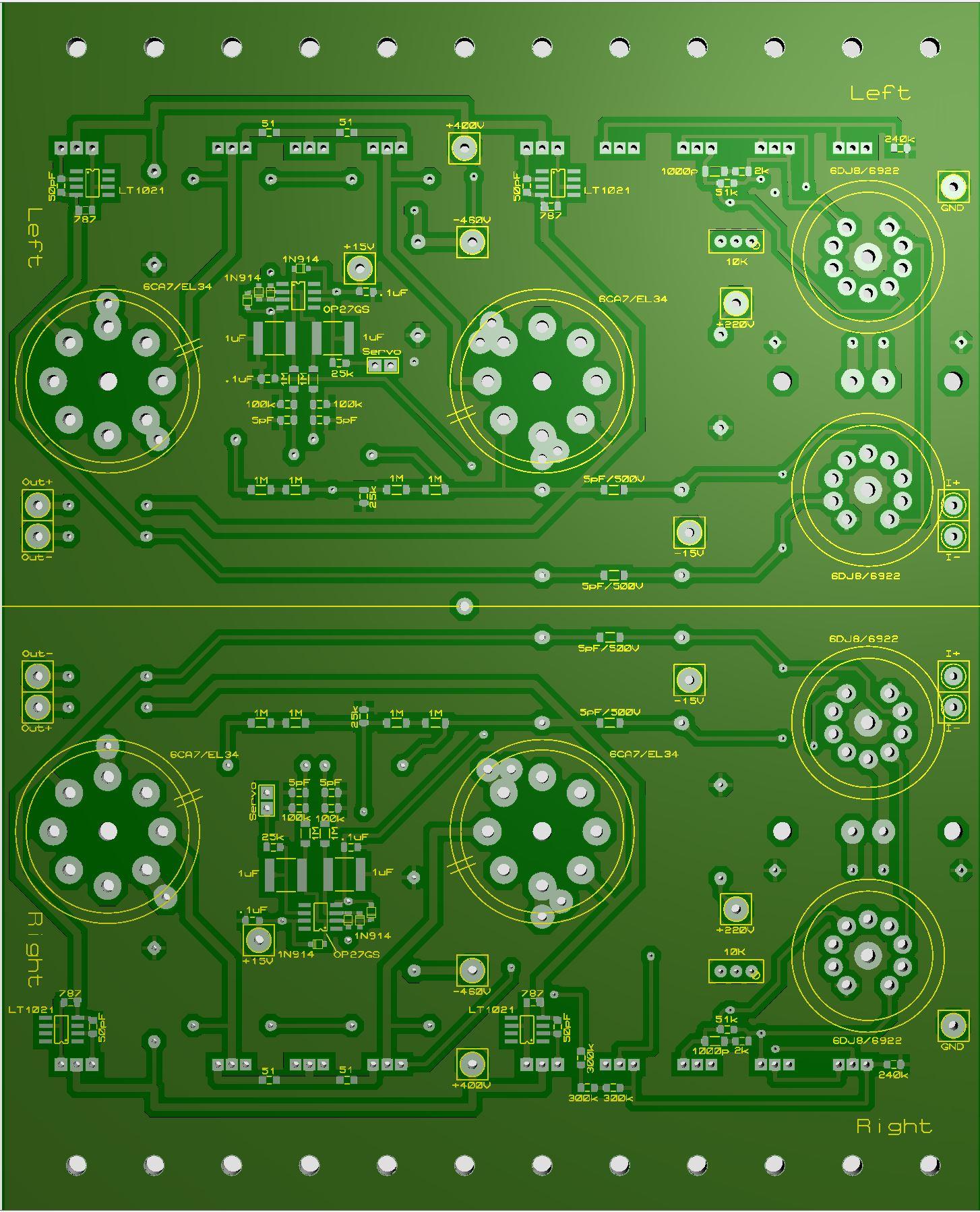
The two mirrored boards are now a married pair. Size 6.3in x 7.87in / 160mm x 200mm. If you want them divorced use a guillotine and cut along the center line.
-
No I don’t. But that’s mostly because it’s beyond my understanding. Maybe someone out there can give us a hint. Made some rework regarding resistors value. Not much to say about it. The R24 and R25 - you probably won’t find 800R easily. Now changed to 787R. The resistor determines the current of CCS. Divide LT1021’s 10 V by resistance and add 1 mA and you get the current. 787 ohm give 14 mA. The four pictures (Top right/left and Bottom right/left) a few posts up are now updated to reflect new values. Schematic for the latest board layouts. Schematic mini T2 version .2.pdf
-
Rushed away to my local supplier and arrived just in time before they closed for the day. Got 0805 180R and 270R. At home they turned out to be 0603 but I managed to get them in place. On the test board I get exactly what I expected and I assume that that’s the case with the amplifier as well. Measured 18.5 V above -HV at bases of Q8 and Q9 with R13/14 @ 330K. I think Susumu RG is a good choice. ToshibaTTC004B is interesting – thanks INU. The smd transistors are also Toshiba.


.png.e5c4ad038a4648274d24dd140ea21bd9.png)