JoaMat
-
Posts
1,448 -
Joined
-
Last visited
-
Days Won
16
Content Type
Profiles
Forums
Events
Everything posted by JoaMat
-
I haven’t run the amplifier with 20K resistors for more than a day. But after switching power on and off frequently I do think this will work. With R1 and R3 at 270 ohm I get 9.0 to 9.1 mA at +220V (each board) and with PSU positive rail set to 400 V a 20K/3W resistor seems to fit perfect. I think gepardcv idea will work and in my opinion it’s absolutely worth trying. Current demand positive rail is approximately 80 mA and negative is 60mA. My earlier statement that a +220 V supply is preferred might be a bit exaggerated.
-
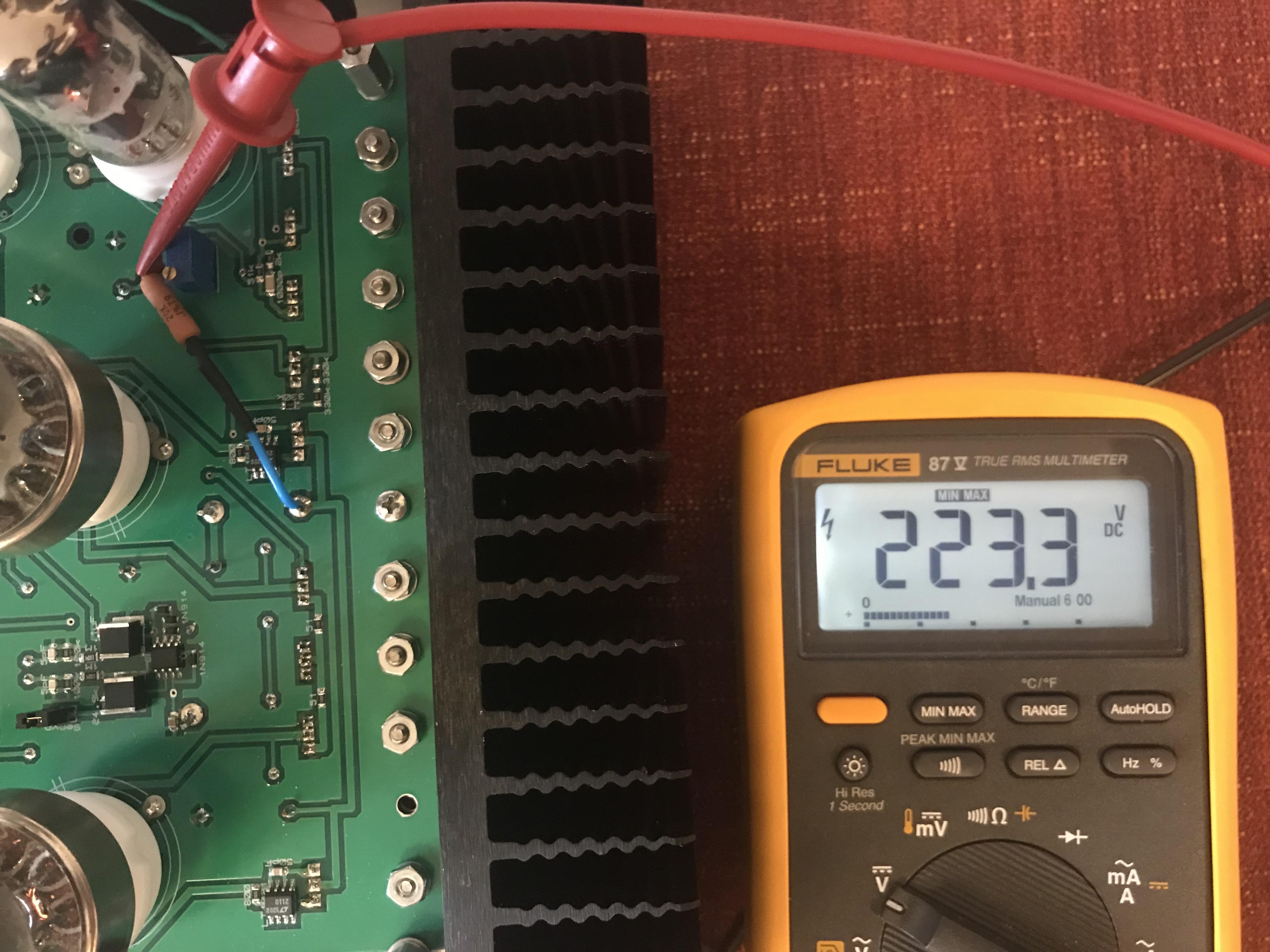
Back from skiing. Zoom in on the Vishay CPF3 resistor and you can read 20K. 400 volts in at the blue wire. The meter is in Min Max mode and it went up to 225.5 V at start up and then immediately down to what you see in Picture. Seems to work. I’ll change the other channel and will test this for some time. I have run the amplifier on a unchanged T2 PSU with +/-500 V and +250 V for a while and that also seems to work alright. Edit: Both channels now with 20K resistors to achieve the +220V. 220.3V respective 219.6V with PSU +400V trimmed to 401.9V on the clocks.

-
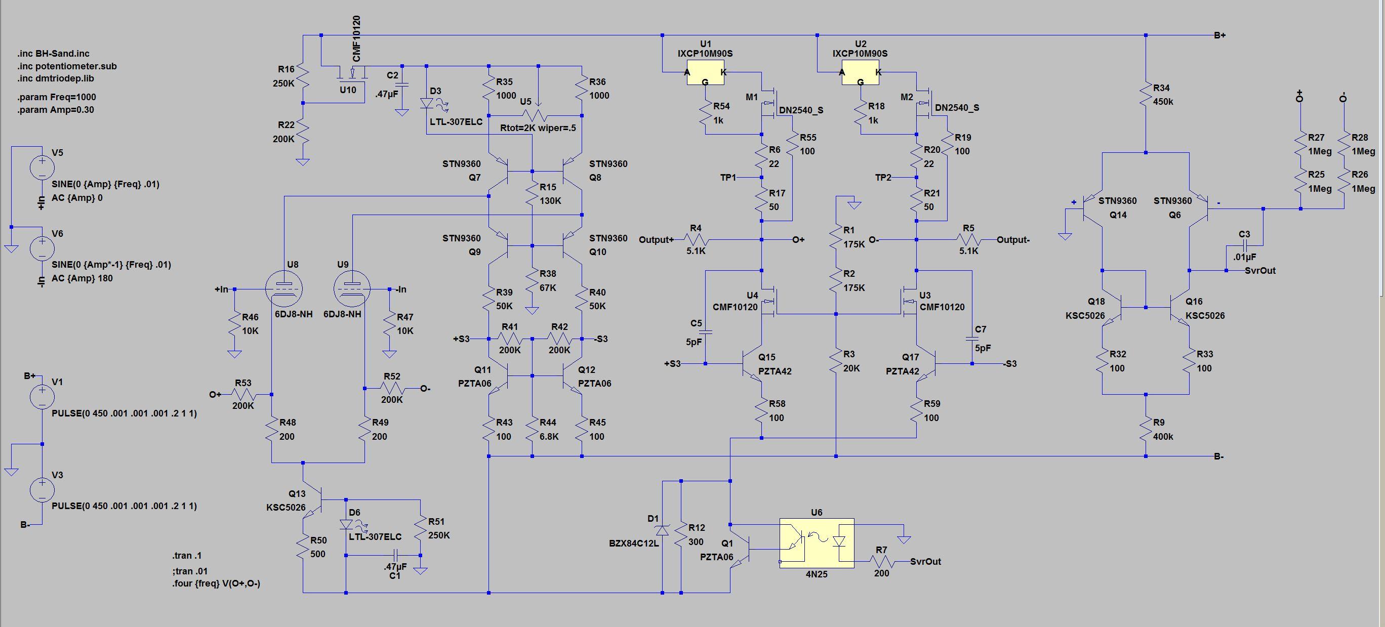
Maybe it’s not wise to entirely rely on a single 20K resistor. A better way probably is to use Zener diodes to achieve 220V as Kevin does with the KGSSHV-Tube-Sandwich. Another way could be using mosfet like Kerry did in below LTspice simulation – see U10, R16 and R22. Ref. Kerry post https://www.head-case.org/forums/topic/12949-stax-t8000-clone-well-sorta/?do=findComment&comment=764504
-
With R1 and R3 at 270R you get 4 mA through each current source plus 0.5 mA LED current. Put a resistor of 20K/2W between +400V and +220V pad on the amplifier board - gives approximately 224V. Someone try this and give a report? I’m on a Ski holiday.
-
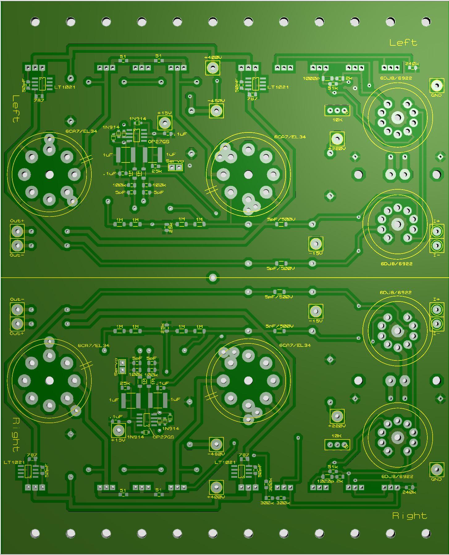
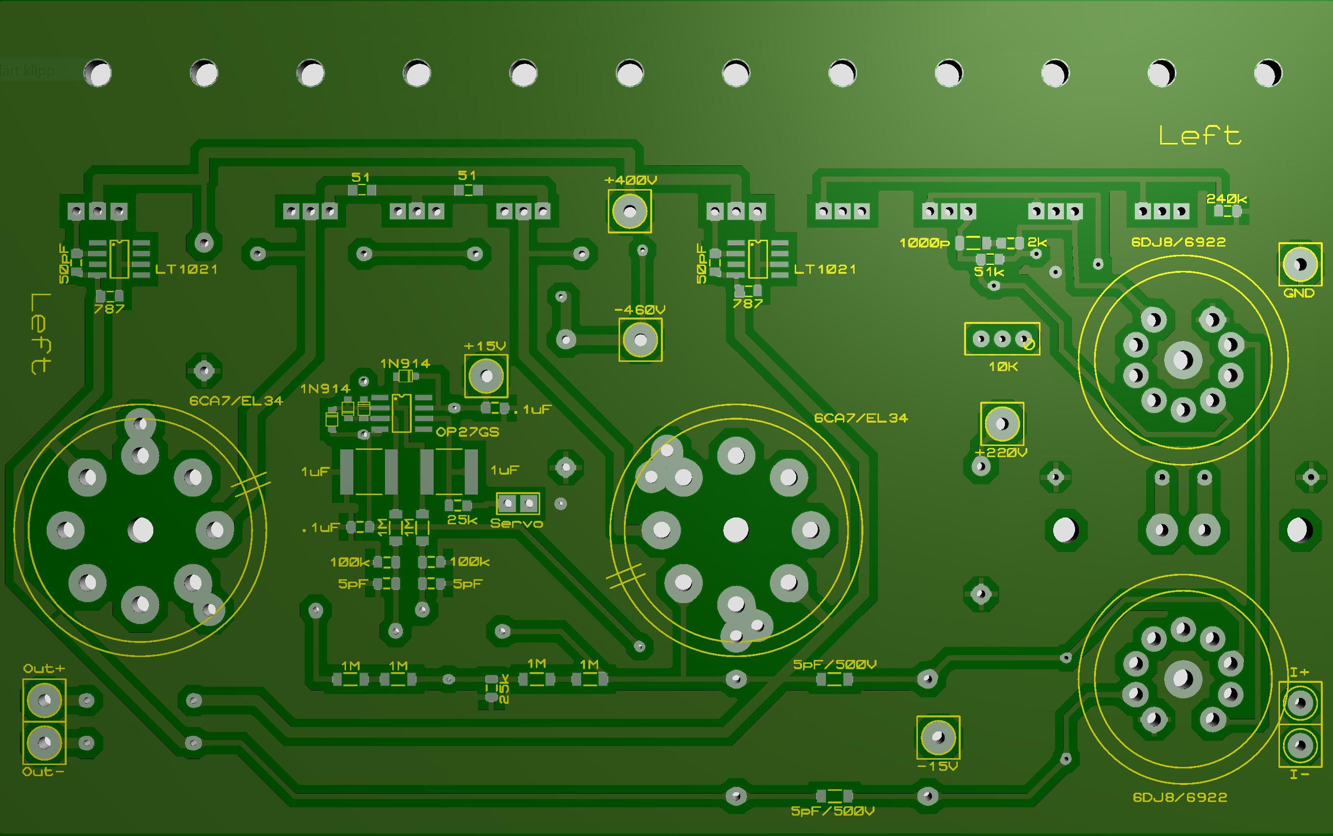
The two mirrored boards are now a married pair. Size 6.3in x 7.87in / 160mm x 200mm. If you want them divorced use a guillotine and cut along the center line.
-
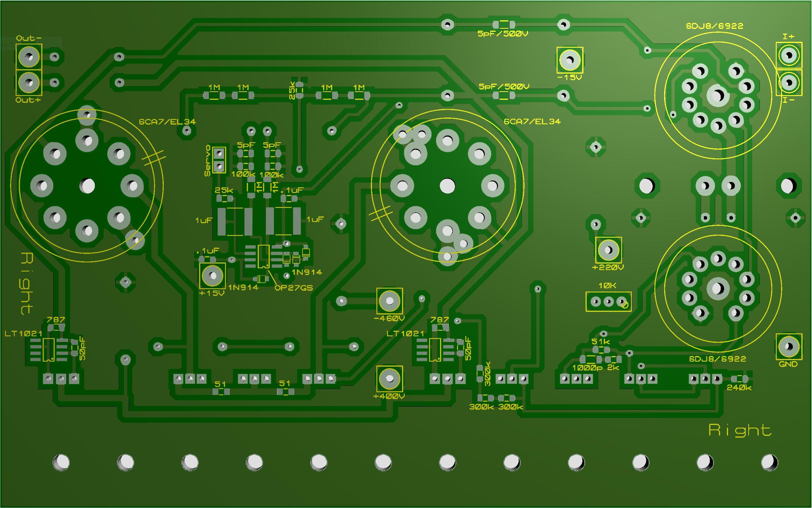
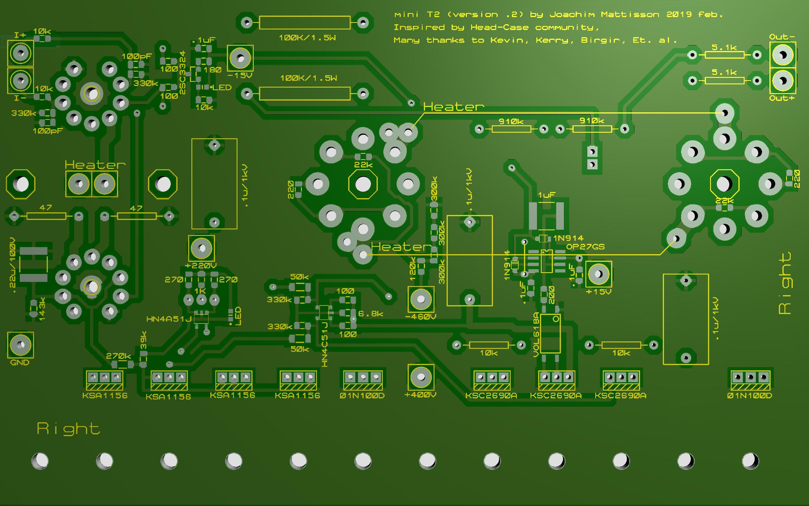
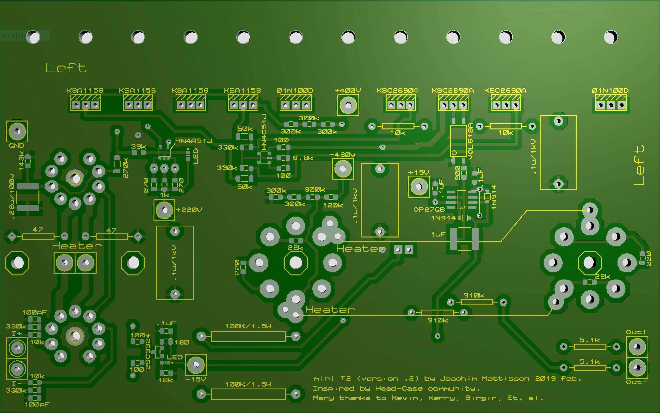
No I don’t. But that’s mostly because it’s beyond my understanding. Maybe someone out there can give us a hint. Made some rework regarding resistors value. Not much to say about it. The R24 and R25 - you probably won’t find 800R easily. Now changed to 787R. The resistor determines the current of CCS. Divide LT1021’s 10 V by resistance and add 1 mA and you get the current. 787 ohm give 14 mA. The four pictures (Top right/left and Bottom right/left) a few posts up are now updated to reflect new values. Schematic for the latest board layouts. Schematic mini T2 version .2.pdf
-
Rushed away to my local supplier and arrived just in time before they closed for the day. Got 0805 180R and 270R. At home they turned out to be 0603 but I managed to get them in place. On the test board I get exactly what I expected and I assume that that’s the case with the amplifier as well. Measured 18.5 V above -HV at bases of Q8 and Q9 with R13/14 @ 330K. I think Susumu RG is a good choice. ToshibaTTC004B is interesting – thanks INU. The smd transistors are also Toshiba.
-
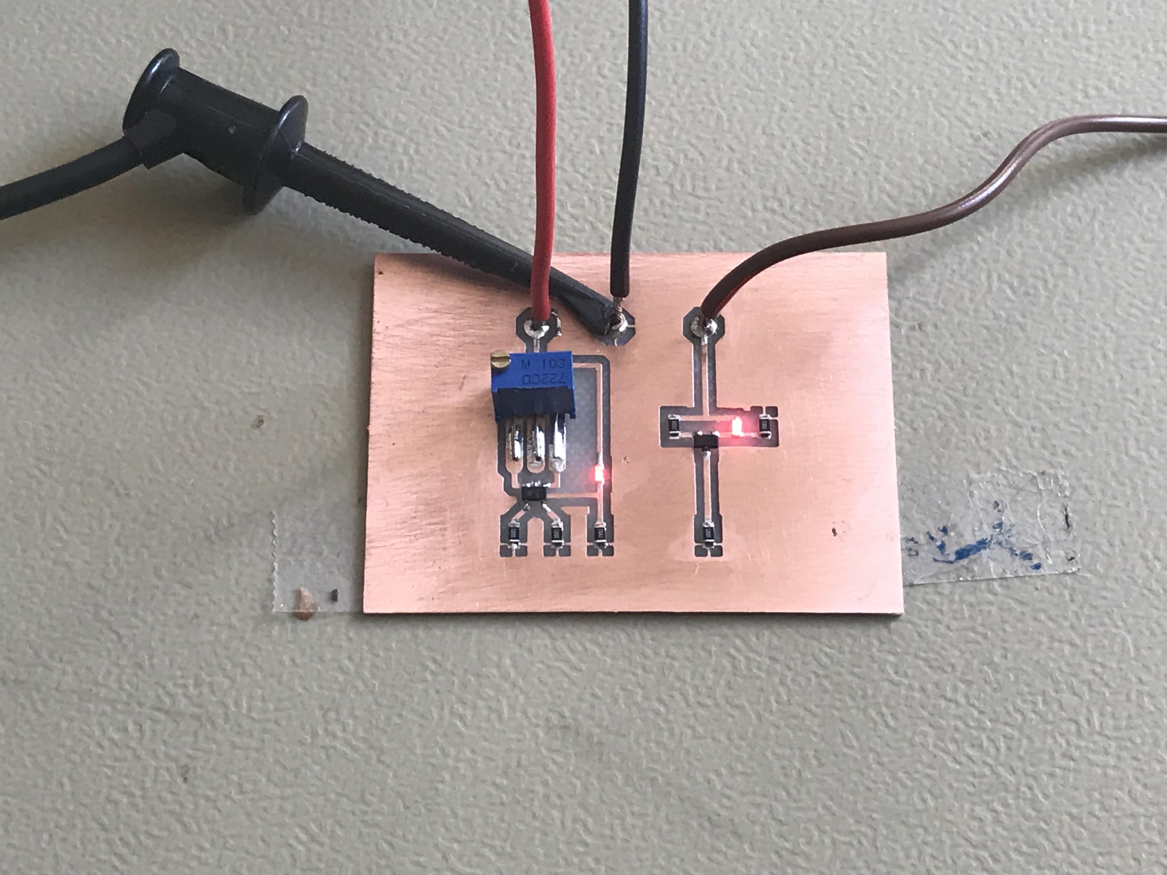
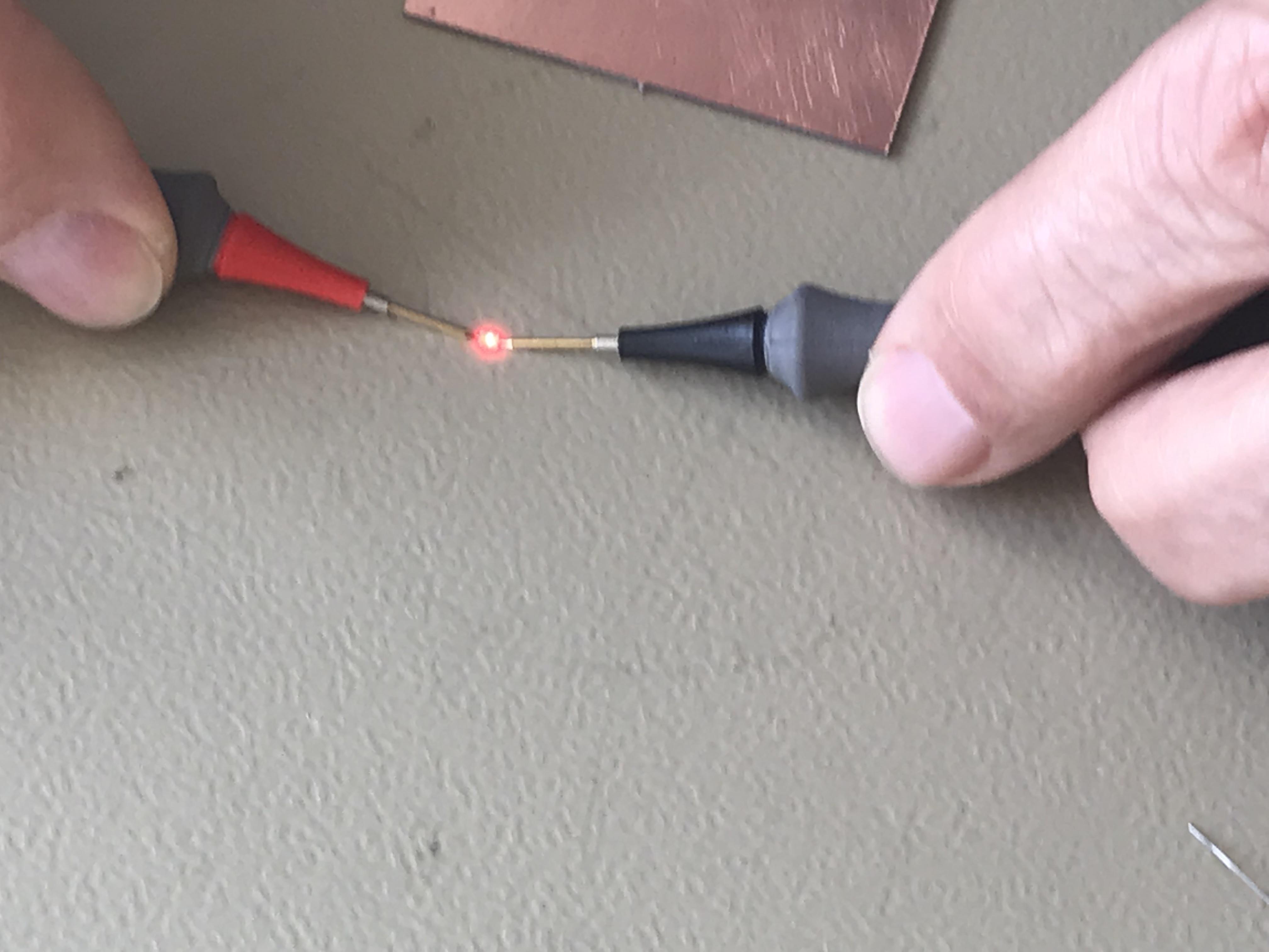
I wanted to find out the currents “produced” by Q1 and Q2. Since I don’t have the courage to stick my nose or test pins in a live amplifier I made this test board today. Measurement on the test board indicates voltage cross emitter resistors at R1, R3 and R9 close to 1.10 V. If we actually have 1.10 V than current through small tubes are 2.6 mA and not 3mA that I mentioned in previous post. The Q1 current sources give 3.8 mA each source. I’m considering changing R1 and R3 to 270R and R9 to 180R. Now days I check for the polarity of the LED TLMS1100 by using DMM in diode testing mode. Positive pin on anode and the other on cathode you get a red light. But be careful the LED will easily pop away and it’s not sure you ever will find it again.
-
R9 is 255R on silk screen on the boards now sent out by Michael. For some time I have run the amplifier with 200 ohms which increases current through the small tubes a bit. I haven’t made any measurements on the amplifier to verify currents but 200 ohms will give something like 3 mA through tubes (T2 has 5 mA). I do think the change improves the amplifier a bit. As I want voltage at base Q8 and Q9 to be 20 volts above -HV, same as the real DIY T2, I’ve today increased R13 and R14 from 200K to 330K. I don’t get +20 volts but it’s closer to it now. R9 on latest schematic is 200 and I think it should be so. R13/14 are 200K on schematic. To follow the DIY T2 you may increase it to 330K. But maybe it doesn’t matter which you choose. Any thoughts out there?
-
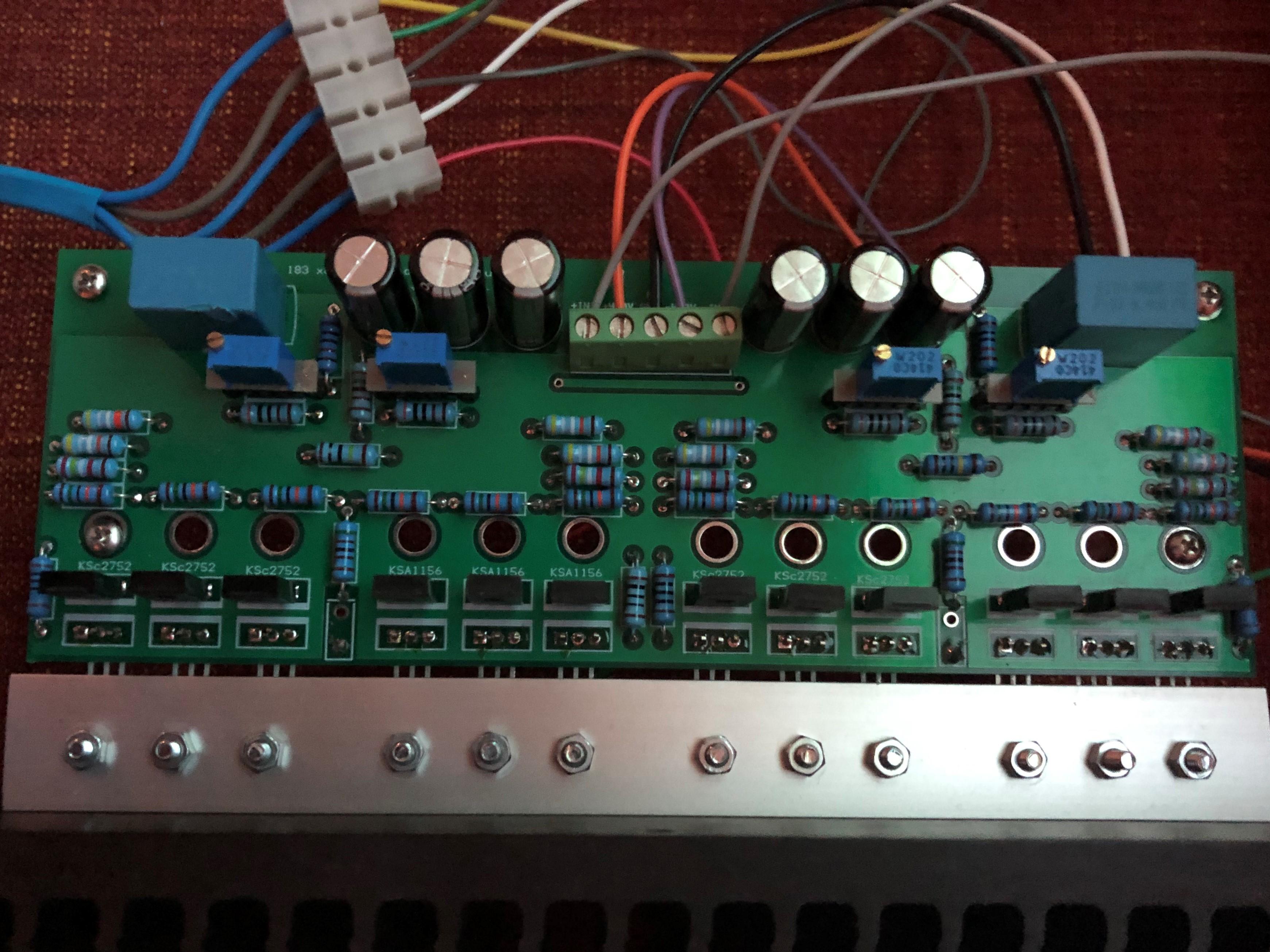
A few points regarding the boards Michael have had made on my gerbers. They are basically the same as my kitchen made boards I made five months ago. The small tube footprint has no hole for the center pin. So far I’ve cut away the center pin on the small tube socket after checking the pin holders to be not to tight nor to loose. One time I got tube sockets where the tubes fell out when turning upside down. So either you have to cut pin or drill a hole. Be aware that upper tube has a trace between the grids that might be to close to center pin. Right board 270K resistor has a 0805 pad (intention was 1206). It’s possible to solder a 1206 resistor on the 0805 pad. If +220V you get about 130 V cross the resistor so Vishay CRCW0805 is OK here. But with +250 V you get close to CRCW0805’s limit of 150 V. Some of component values on silk screen are poorly place and almost unreadable. The blame is entirely on me, I’m very sorry. There are four octagons on bottom side. One at each big tube socket center hole and one each side of small tubes filaments connections. Here I have standoffs. A few comments on updated layouts. Small tube footprint with center hole. 270K resistor pad corrected - now 1206. Silk screen remade. Pleas notify me if there is any left that needs additional attention. Now “value” of connections on both sides (except heaters). No terminal blocks on my boards. Top right. Updated 2019-02-27. Bottom right. Updated 2019-02-27. Top left . Updated 2019-02-27. Bottom left. Updated 2019-02-27. I call above version .2. My kitchen made and Michaels are version .1. Regarding this amplifier - there is nothing I've invented. I just have picked up different things and tried to put them together. As: Opto servo (the only offset servo you need) by Kevin. 01N100D/TL1021 current source by Kerry. Schematic of Stax T2 provided by Kevin, Et. al. Schematic of Stax T8000 provided by Kevin and Birgir. Etc. etc. Thanks for all knowledge, information and inspiration from you DIYers and Head-Case members. Please look for errors or other issues.
- 286 replies
-
- 10
-

-
OK – Connected an unmodified T2 PSU. Raised voltages to +250 and +/-500V. Top 6922 anode voltage sits at 227V and grid at 78V. So far it works. Will run this for a while and check for darkening spots on the boards.
-
I want to make some minor changes to the layouts. After that I think more boards will be available here. Should not take long.
-
Board size 160mm x 100mm. Sure it's possible to shrink it, but that will be the micro T2, then we have nano, pico ….. Thinking about the possibility to use an unmodified T2 PSU. If applying +250V instead of +220V you get +79V at upper 6922’s grid and +230V at anode (with no changes on the board). T2 has +69V resp. +200V. Power at HN4A51J goes up from 2 x 76mW to 2 x 87mW, so still OK I think. Question is if the higher tube voltages make any difference. But I don’t think it’s wise to put 48V cross HN4A51J when bringing down anode voltage to +200V (with +250V supply). As for +/-500V; no problem with 01N100D it’s a 1000V device. I do think it might be possible to use original DIY T2 PSU. Has to be proven.
-
I don’t really want to make any comments on how things sound and compare them. Mainly because it makes me feel uncomfortable and I also lack the ability to analyze the sound. Anyhow I’m very happy with “mini T2” and I want to think that it is quite similar to THE DIY T2. Now I have put the original DIY T2 in the closet and I don’t miss it. I still have my modified T2 in our summer cottage and I like that one as much as the “mini T2”. But I have three more original T2 boards and all sands for them – no duck feeding the next couple of years.
-
-
Oops. Schematic posted above uses 2sa1486 in the current tunnel – my first boards had the 2sa1486. Schematic in the link uses twin ksa1156 in the tunnel and the boards have the twin ksa1156. The boards Micheal and Jose have had made are created from the linked schematic.
-
Ajaj! That -400V is something from earlier schematics I worked with and I obviously forgot to remove it. The -400 V potential is created by voltage divider R53 – 56. Otherwise the schematics are identical except for that components have different coordinates (I hope, crossing fingers). Thanks for noting it, Steve.
-
You can use +/-450V for +400V and -460V. But I suggest you find a good way to achieve +220V.
-
-
Oh! I forgot Kerry’s micro GR - that would really be something. Link
-
Well, I changed the voltages as said above on a T2 PSU that is a bit different from the original. I used those lower voltages for my T2 for some time before I built mini T2 and it worked great. So if you dare to lower the voltages on your T2 PSU and remove the 7812 and 7912 and put in the https://www.amb.org/audio/sigma78_sigma79/ set to 15 volts. Then you have an universal PSU. I haven't tried AMB sigma78/79 in T2 PSU but someone has to...???
-
I’m using a modified T2 power supply. +250V reduced to +220V. +/-500V and -560V are reduced to +/-400V and -460V. +/-12V increased to +/-15V. Filaments as original. But the -400V is not used at all with this amplifier.
-
A very early layout attempt. Have to figure out how to spread the parts. Board size 2.65in x 0.87in.
-
Increasing trimmers resistance always increase corresponding side’s current and vice versa. If upper trimmer (ksa1156) increases corresponding side’s output voltage increases and the other decreases. If lower trimmer (ksc2752) increases corresponding side’s output voltage decreases and other side increases. So far I’ve preadjusted all eight trimmers to the same resistance. Resulting in roughly the same current of all for channels and in an output voltage of some positive volts - all good and not needing any further action. To me it has been a bit tricky to turn all trimmers to achieve better balance and offset than when the preadjusted.
-
OK, now I’ve reached further. Replaced all eight 2K resistors with 2K trimmers. Makes it easier to change the current. Set at 1.6K current start at 2.5 mA and climbs to 4.5 mA. IMO it’s still an interesting amplifier and I believe it’s possible to build an all SMD version.