-
Posts
1,471 -
Joined
-
Last visited
-
Days Won
16
Content Type
Profiles
Forums
Events
Everything posted by JoaMat
-
Think I like trimmers. Instead of servos – miniature stepper motor driven trimmers controlled by Arduino?
-
BDent has made a fortune out of me due to them stories.
-
To find out I removed Q10 (also removed vol618) and replaced it with 1K trimmer (just put it in Q10 position) to control the offset. With balance trimmer (jumper removed) and offset trimmer I’ve no problem to manage the amplifier, but this is just after a day. Maybe I tell more later.
-
I haven’t removed “current limiter” resistor – here I use 15R/3W – just removed the 2n3904 transistor. I’m only used to 4 separate heater windings so I can’t tell about running all big tubes as you do. Mini T2 has big tubes heaters tied to roughly -400 V via R53-56 voltage divider, so you actually connect left and right channel’s dividing points with your single filament transformer. My brain is to slow to figure out what, if any, implications that might have. Perhaps someone out there can enlighten us. But never use same heater windings for big and small tubes. Small tubes don’t like heaters to be tied to -400 V and besides their heaters are tied to ground via 47R resistors.
-
Thanks, good to know what components that are at risk. I’m using a KGSShv style PSU and I’ve a small inventory of FQPF8N80C, 30V Zener and 15R power resistors and so far that has been enough. Also omitted current limiter since it hasn’t protected me. One other question, @jose. Do you have four separate 6.3 VAC for the tube heaters?
-
Great, quick recovery. What parts in GRHV needed to be replaced?
-
I’m sorry for your misfortune. Did it happen direct after you power up the amplifier for the first time?
-
Nice! Interesting build indeed. Making generic boards satisfying all builders is not easy. Myself - I do like mirrored amp boards without terminal blocks. Until phase 3 – we wait for phase 2.🙂
-
It’s some time since I disassembled the headphone and my memory isn’t the best, anyhow. Remove earpad fixed by double sided tape and remove the two screws now exposed. Gently remove the now loose inner ring one none ear side and all inner parts are accessible. It’s easy to detach earcup from headband, one screw only, and cable – then you have the earcup completely free. I believe it’s fairly easy to work on the headphone, but as always be careful. Personally I think Kaldas is an overall nice design. Good luck.
-
Warning!!! I’ve tested sot 23 even a 500V/0.5W piece. Three times it started OK, but after some time (several power ON/OFF and hours) without a warning one of Q30/31 has popped and corresponding resistor totally destroyed. Furthermore two ksc2690 (k216 eq.), one fjpf2145 (c3675) blown and damages to PSU. If you don’t know what you are doing (I obviously haven’t a clue) don’t change Q30/31. Let them be 2sc3675 (or fjpf2145 - I used it for more then six years now).
-
-
A faulty ksc2690 (2sk216 substitute) north of one of the batteries. It tested alright on transistor tester but at a much lower hFE than specified.
-
Problem solved. No hum or noise that my old ears can detect.
-
Thank you. Them pins looks very interesting indeed. Regarding my current project. Goal with it was to build a T2 on an original board with all modern components. After a visit in the ditch I returned to the narrow road. Rebuilt the batteries to original LED version on the board. Had to change some resistors as I reduced voltages - battery is 640V instead of the original 740V. Furthermore the change to fjpf2145 instead of 2sc3675 called for a Darlington par out of pair of fjpf2145 in batteries. Very easy to make a Darington pair on the original board. Yellow Teflon wire from base to a via on the board – perfect and the via has a perfect diameter. Some components (ksa1220, ksc2690,ksc1008 and j112) have different pin out as the original ones so I twisted their legs to fit the board. Thanks Michael (mwl168) for how to bend legs on the ksc1008. Bottom line: I believe I’ve built a decent version of DIY T2 with all modern components. I’m satisfied and am about to make myself not so sober (it’s Friday evening). P.S. some problem with one channel, unwanted noise and hum. Happens now and then if you have T2s…
-
Nice balance servo. Here is an old T2 board with small boards with HN4C51J replacing 2SC3381. By the way Kerry, what kind of pins do you use with your small daughter boards?
-
Yes, of course.
-
No twisting they can't be at same side of the board due to pin layout of c3381.
-
You use a board without 2sc3381 footprint?
-
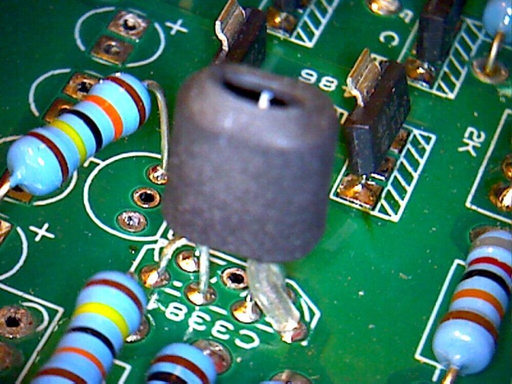
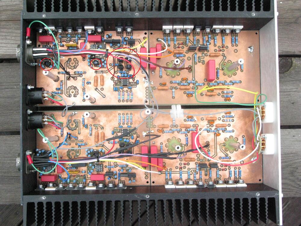
I’ve used mpsw06, big brother to mpsa06. Here in my modified T2 (mpsw06 in red circles). Here in a DIY T2. Both pieces on same side of board and held together by heat shrink tube. Than you have to twist legs so they look like a Dancing Fool. A lot easier just to stick a pair of TO92 from opposite sides. Want surface mount? HN4C51J.
-
Now I’ve tried them. KSC1008, put them in like this, one from component side and the other from solder side. Save you a lot of money. J112, changed 22K resistor to 13.7K then able to adjust to 6.55V. Doesn’t save you so much money.
-
Here is a T2 on original DIY T2 board with all modern components. High voltages decreased by 100 V to satisfy fjpf2145 and ksa1156. Batteries are on small daughter boards. There is annoying hum on left channel. Right channel is silent so hopefully it’s possible to get rid of the hum.
-

Kerry Design mini GRHV\GRLV and JoaMat mini T2 Group Buy
JoaMat replied to mwl168's topic in Do It Yourself
I’ve been using 1.6mm/1oz boards for some years now and I believe they are sufficient in most cases. James (jamesmking) has built one mini T2 and I’ve built two with 1.6mm/1oz. -
So you have 7.43V with the 10K trimmer at endpoint? What is the voltage cross 22K resistor of the other battery?
-
Power supply is back. Replaced a number of FQPF8N80C, 30V zeners, 15R power resistors, one 2sa1486 and one 2k resistor. What actually killed the power supple (except the guy that should be feeding ducks) has to be investigated…


