JoaMat
High Rollers
-
Joined
-
Last visited
Everything posted by JoaMat
-
A less contagious and unknown mutation? No need to. Informative posts are always appreciated.
-
Happy Birhtday, Kevin!
-
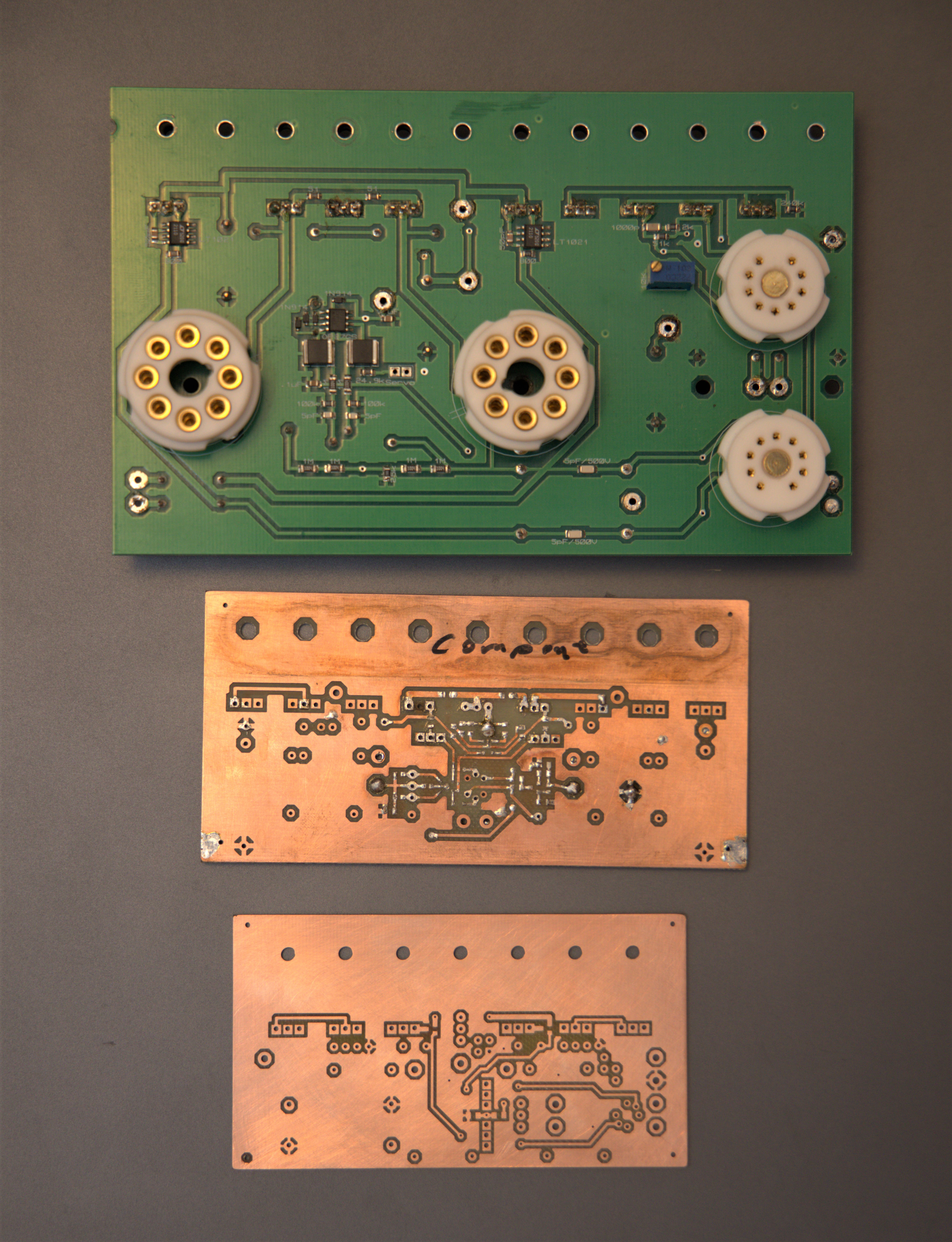
Great, this is the first time I see them boards, even if it’s just on photo. I want to add that one name is missing on the boards – Kevin Gilmore. Kevin added a few things like trimmers to set output current, test points to measure it, terminal blocks, part values, labels etc. etc.. During the work with the boards he taught me how to quickly make a mirrored (as far as possible) board from the first one. Thank you, Kevin. Welcome to Head-Case, Rich (sweetleaf)!
-
Thanks a lot for this project, Kevin and Kerry. At least the amp sections seem doable , even with my old eyes and clumsy hands. Is the board two layers or worse?
-
Many thanks Todd!
-
yep
-
This is how my first attempt to mill a pcb stencil turned out. The aluminum sheet comes from a Burgenfels beer can.
.thumb.jpg.84bc2c6d435c45bb9295fa0bd8524f1b.jpg)
-
Thanks for the input. I use the software FlatCAM to convert CNC files from gerbers. Eventually I found the way to invert a gerber with just one push at one button. I’m very embarrassed I didn’t noticed the button, it has been in front of my nose all the time.
-
Is there any easy way to invert (“convert from positive to negative”) a gerber file. I want to invert the solder paste gerber file – then I think I can make a CNC file and mill PCB stencils. Or at least I can try…
-
I always do smd soldering with fin tip solder iron and after a long time of practicing I feel quite comfortable with that. I’ve tested with hot air station and with proper amount of solder paste on the pads and when using low air flow I managed to solder without components blowing away. And it’s a nice feeling seeing a component nicely aligning up on its pads. But I prefer the soldering iron technique. Me and solder paste don’t mix well. After a while the whole table is a mess and I even have solder paste on my nose. With some practice I’m sure everyone can do smd soldering, but it can be very frustrating initially.
-
-
Then I found this... ...love this thread.

-
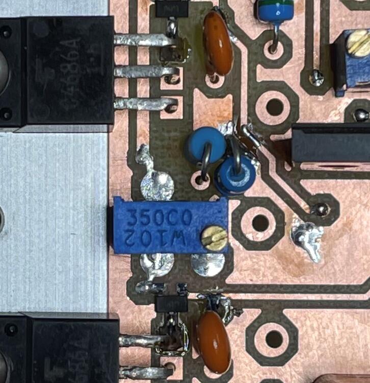
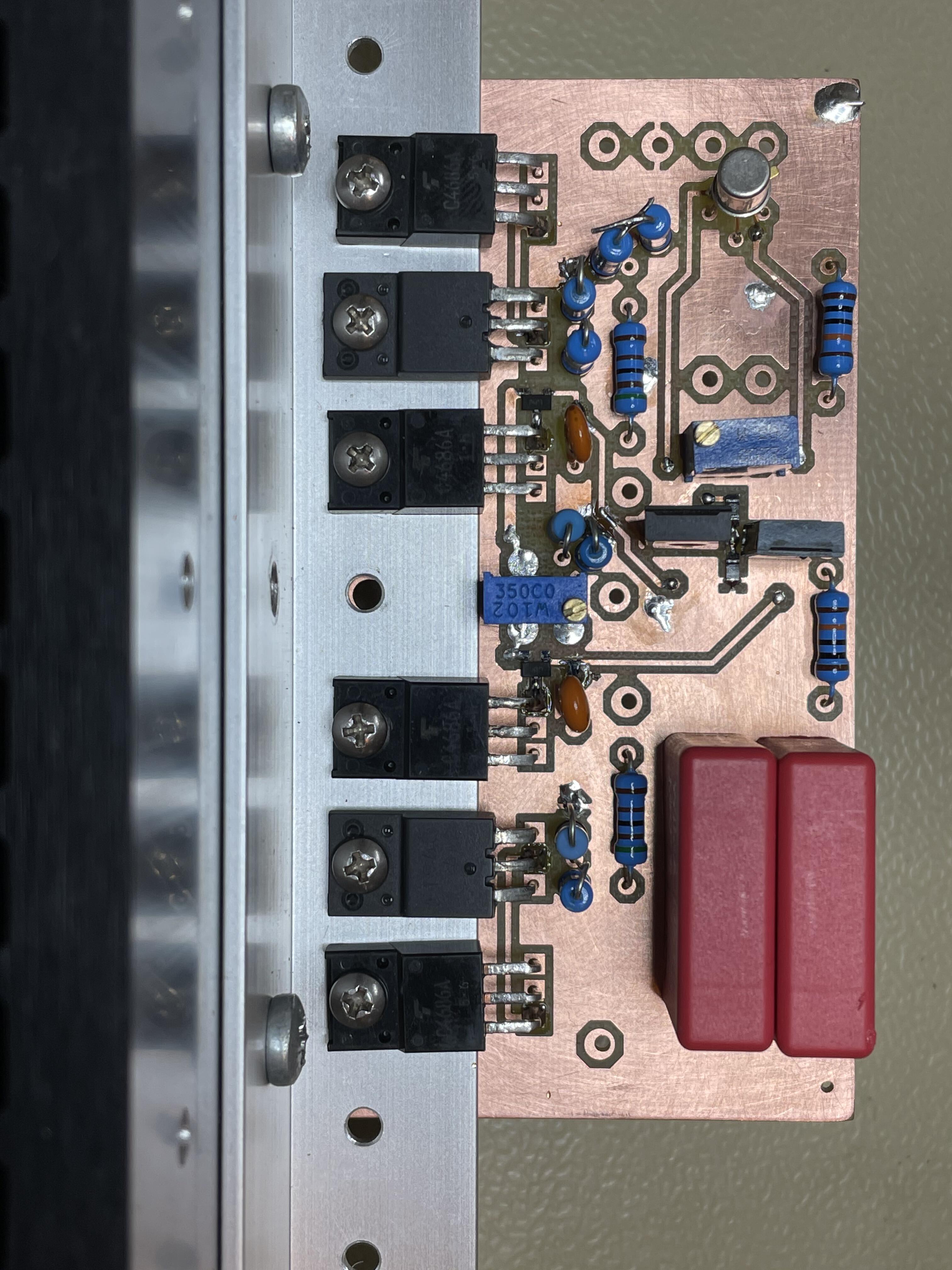
This was not meant to happen. Modifying the original DIY T2. But now it’s done. I couldn’t resist to change the output current sources. Replaced two 2SA1486 with single 2SA1968 and removed four 150K resistors. I put a small heat sink on the transistors. They will dissipate half a watt or so. 2SA1968 is a 900V device, but I’ve reduced high voltages to +/-400V so that should be fine. By the way the 2SC3675 is also a 900V device.
-
I might help you with a few. Ping me if interested.
-
Omit zeners along with the drop down resistor if you have the 300V supply.
-
It’s like being an archaeologist I imagine, very welcome @chocolates!
-
-
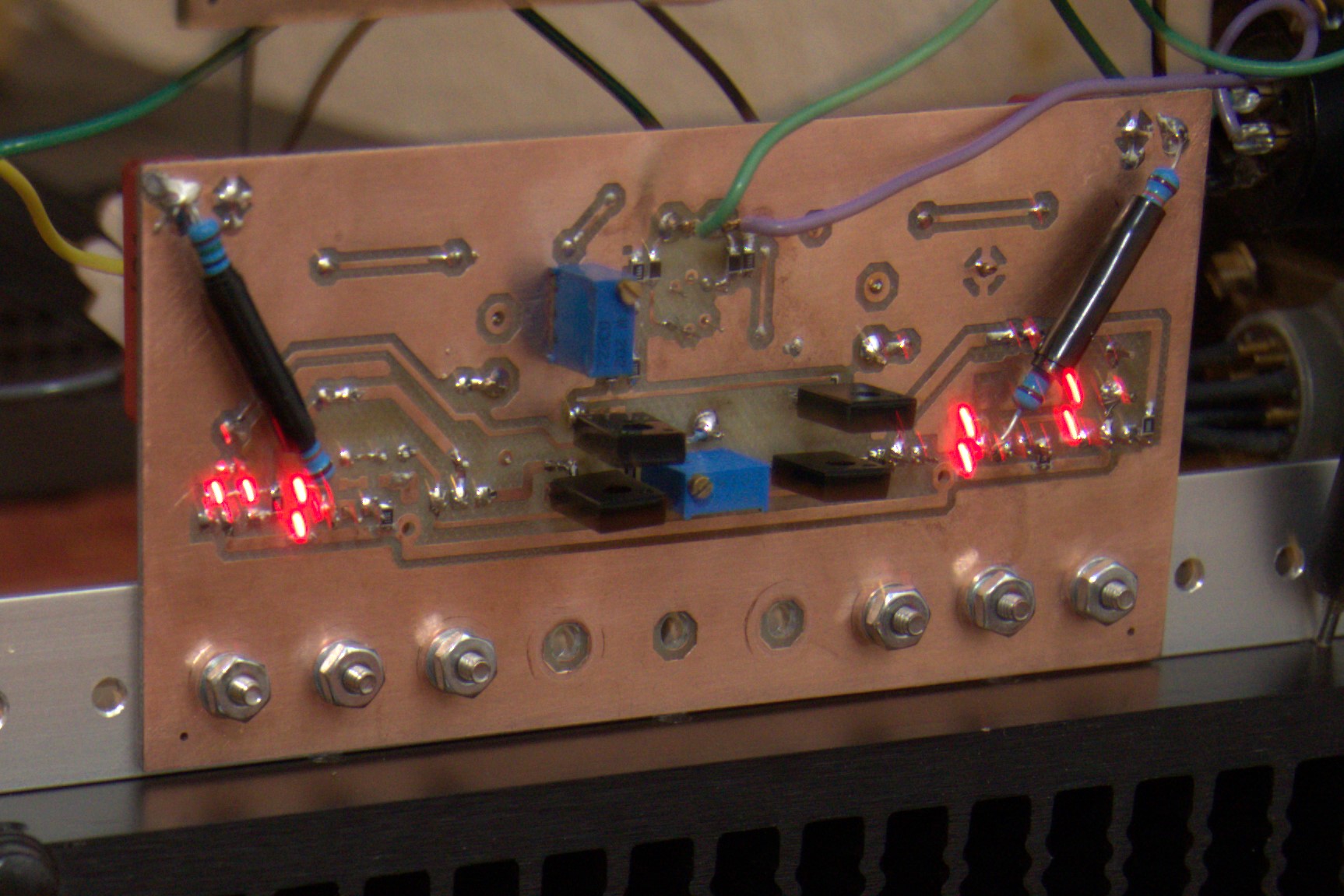
I’m working all week around. Today I milled left channel board similar to the right side done yesterday. Here it is. For some reason the holes of big pads aren’t centered. Grrrrr. Three round tanned pads close to offset trimmer are test points. Measure voltage cross 100R resistors R25 and R31 and you get an idea of current through output stages. I got 1.014V and 1.007V so approximately 10mA.

-
Just completed the work with another board (right in picture below) and it is now up and playing. Yesterday I milled board similar to one just done. But unfortunately I forgot to correct the resistor string mentioned here... ...so it died in thunder and lightning. Made a new corrected board today and moved the good parts from the faulty board. Also had to fix the PSU. Due to all earlier disasters I know which parts that need to be replaced…
.thumb.jpg.ceed377f178368c38266b9f9adff48e4.jpg)
.thumb.jpg.1bec3dc441f5dd1afbecaef9d5e2fcfc.jpg)
-
-
-
-
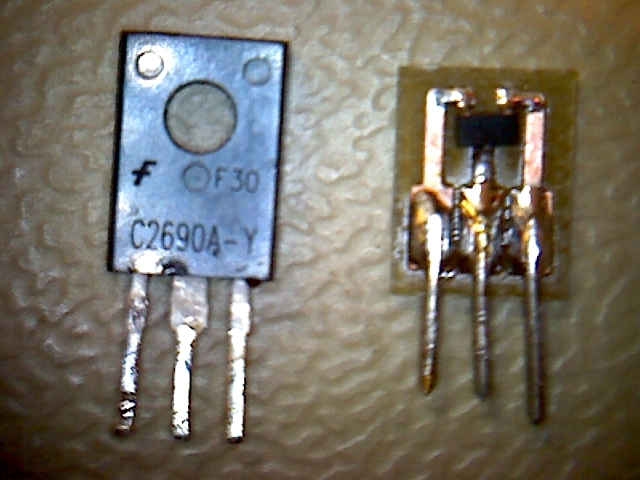
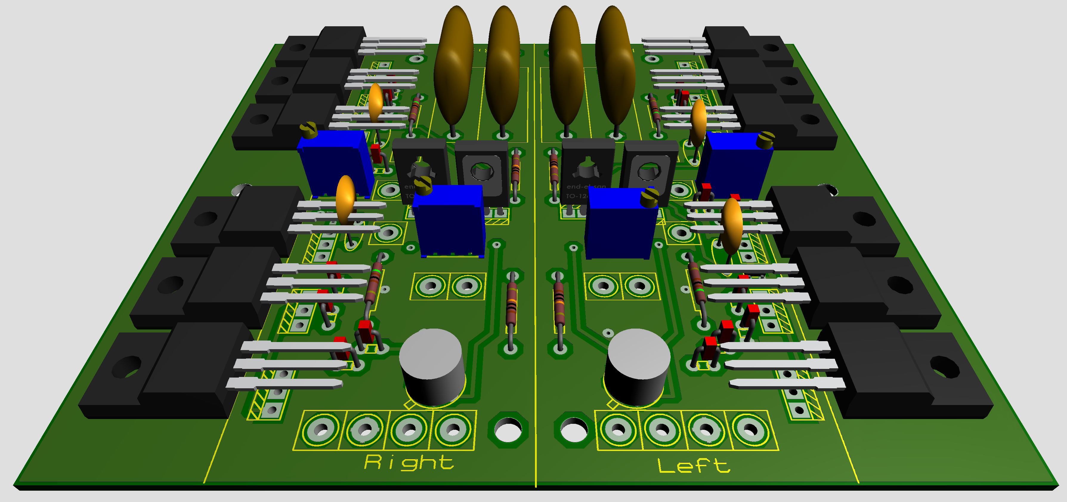
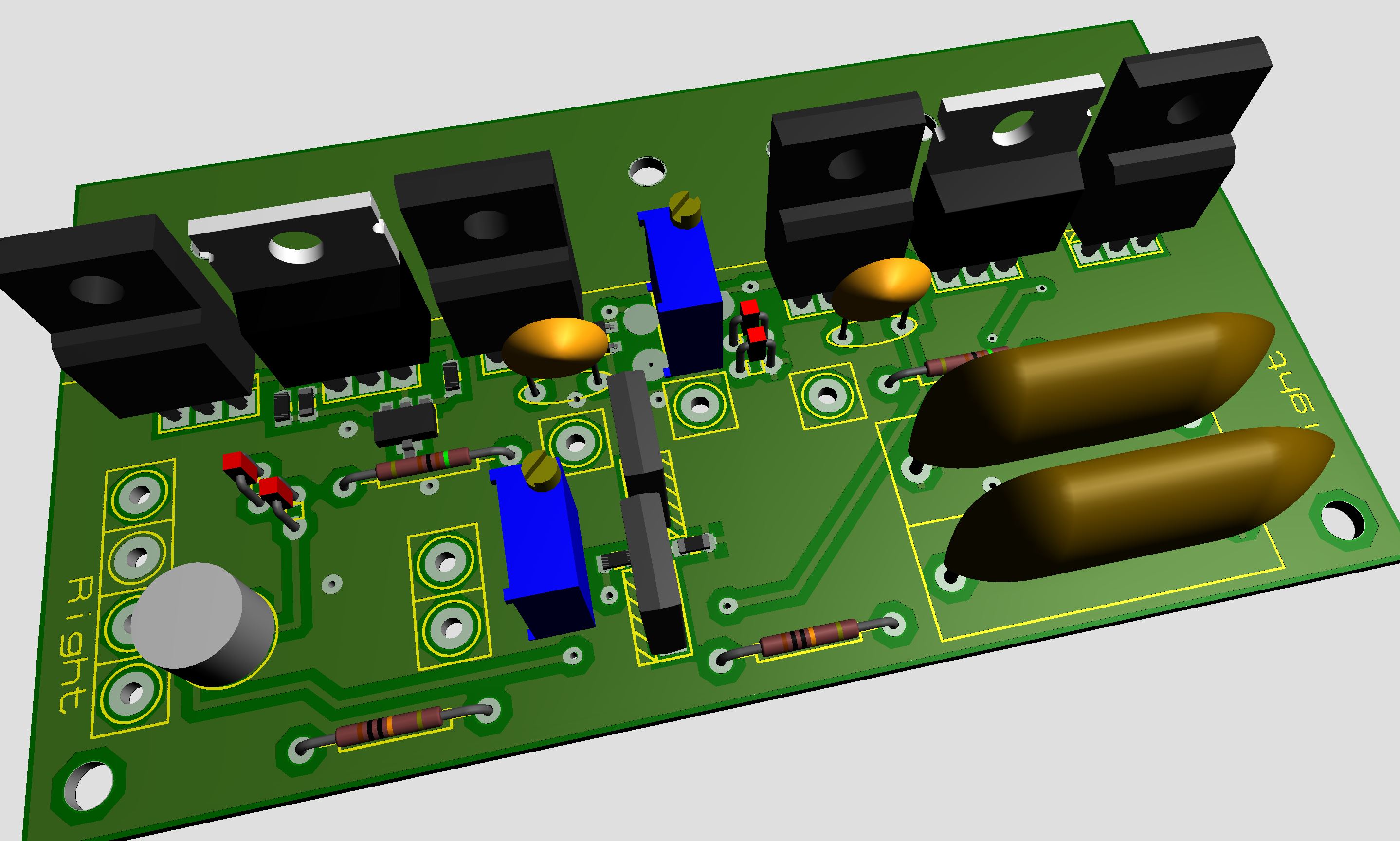
This is probably pushing it too far. Changed ksc2690 for 2sc3324. Board size now 99mm x 112mm or 3.95in x 4.44in. Looking at the 3D visualizer it seems doable. I've found a way to lay down the transistors flat but not how to bend the legs. Anyhow it’s fun working in Proteus. You can create the most odd things.

-
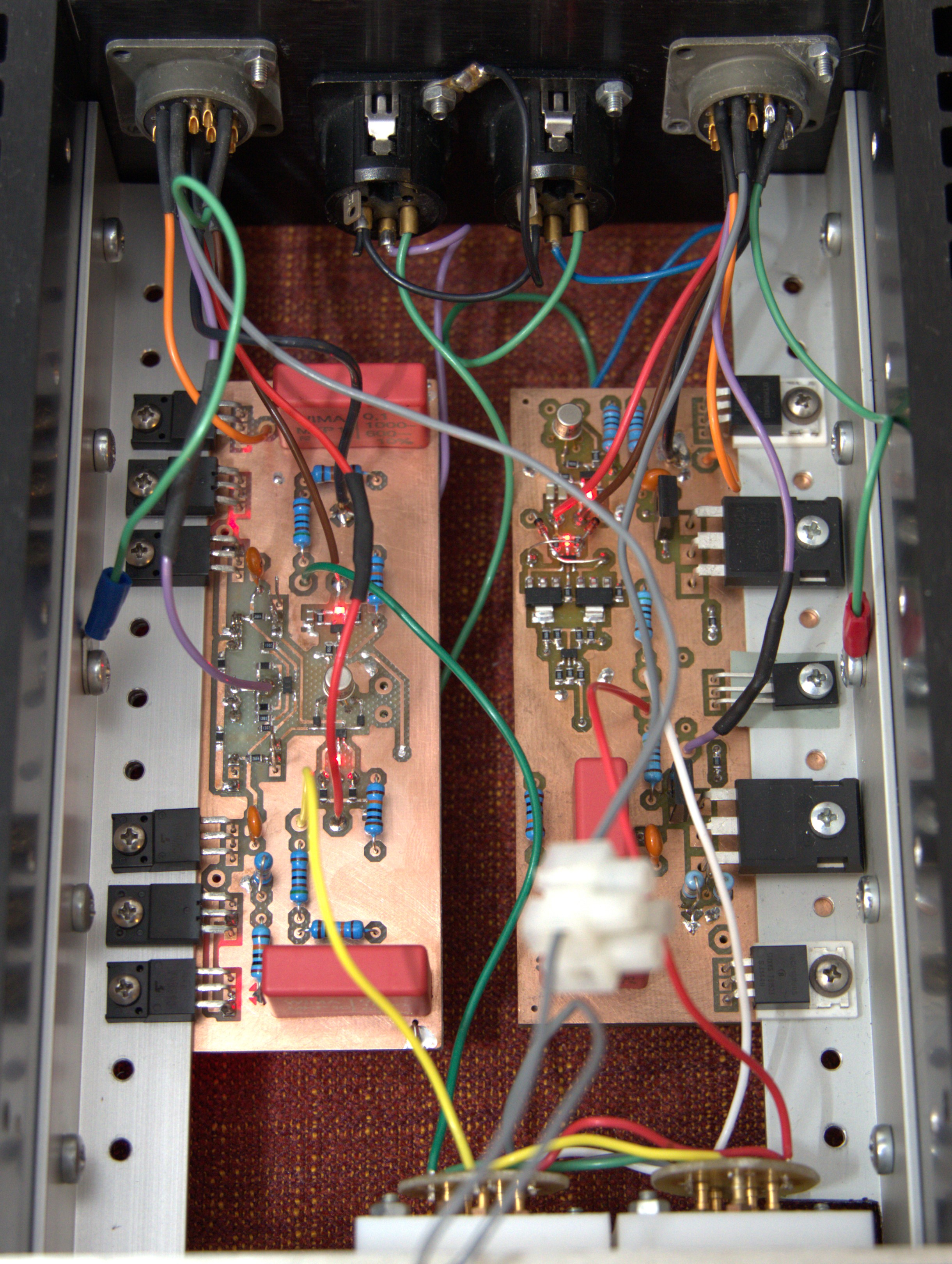
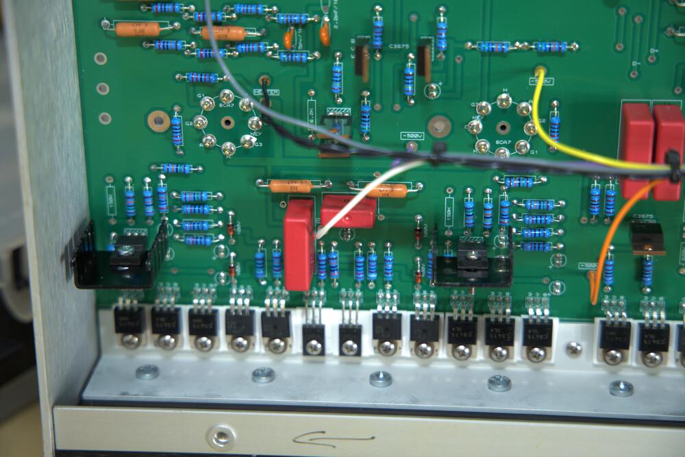
Schematic a few posts up is updated and now reflects what I’ve built. Changes: R21 – R23 and Q3,Q4. Picture from top. Carbon board to the right with ceramic insulators. New thing to the left. All transistors (2SA1968 and 2SA4686) on bracket are insulated and don’t need ceramic insulators.

-
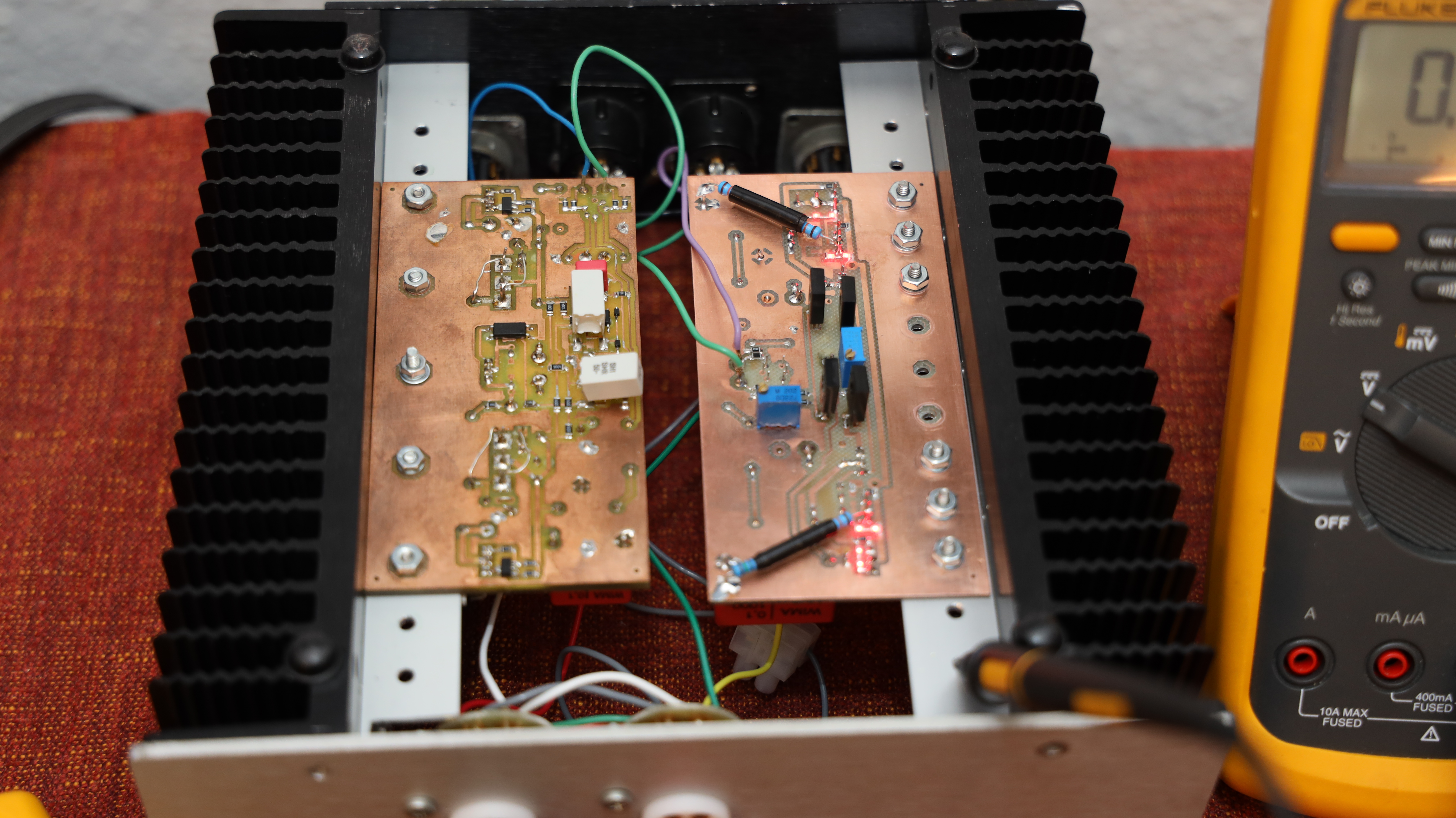
Milling process went smooth. Here is the board populated with components I had at hand and it works alright I would say. It is playing in pair with a Carbon I built three years ago. The Carbon to the left but its actually the right channel. Amplifier is upside down. I put the trimmer on bottom side – I forgot that this isn’t a tube amplifier with none component side facing upwards. In schematic posted earlier there is a couple of 2SA1486 but I took a pair of KSA1156 instead which is OK as HV is +/-400V.


.jpg.08a7af3901cde71151eef074af2663d4.jpg)


.jpg.820221080f8461a56bd5195bfdeb563d.jpg)
.jpg.5f5ad203af4a7128beb9e3f499c140a3.jpg)