


JoaMat
-
Posts
1,471 -
Joined
-
Last visited
-
Days Won
16
Content Type
Profiles
Forums
Events
Everything posted by JoaMat
-

and now for something completely different part 3
JoaMat replied to kevin gilmore's topic in Do It Yourself
My guess is both cases are 2U… optical visual illusion makes them 1U? -
Happy Birthday!
-
Datasheets are nice.
-
Thanks guys. Now I know I don’t understand… hopefully I’ll learn something later...
-
0.4A at 11.1V suggests … something like 3mA each channel?
-
Check this partco.fi/en. They claim they have 8 pieces of 2SK216 in stock at EUR 4.28 each. I don’t know anything about Partco. But Finnish people tend to be reliable. 03/01/2021. They seem to be gone.
-
Very nice headphone amplifier indeed. Please don’t wait too long with your next project. We want more.
-
Nice! So with one 5000mA 3S LiPo pack I’m ready for a 10 hours hike? Lovely. P.S. I want one now.
-
@Blueman2 Have you tried any of the alternative devices to C2M000170D in a Carbon amplifier?
-
This? kgbhultraminipsv4.zip
-
Kerry Design mini GRHV\GRLV and JoaMat mini T2 Group Buy
JoaMat replied to mwl168's topic in Do It Yourself
@starcat I have boards. Ping me if still interested. Location Sweden. -
Most, if not all, public published GRHV boards are with c2m1000170d but if a bit creative you might use fqpf8n80c. If you do - please tell us how it turned out. We have to find ways to tackle unavailable parts.
-
Eventually I managed to dig up some money. I also had a brand new pair of Stax pads at hand. Thanks for the advice. I’m really happy with this Headphone.

-
Megatron Electrostatic Headphone Amplifier
JoaMat replied to kevin gilmore's topic in Do It Yourself
like a Gran Reserva
-
`
-
and now for something completely different part 3
JoaMat replied to kevin gilmore's topic in Do It Yourself
Report from cuisine de joamat. One side of the balanced board works alright – able to set output current and offset is within a millivolt. The other side – output current controllable but servo doesn’t work as desired, offset, varies round plus two and a half volt. Here is an aerial picture of the output board. I’m not so happy to dive in with test pins in there… and servo parts on the bottom side. …maybe I should be satisfied with one working side out of two possible.
-
94 seconds of Mozart: Allegro in D Major, K.626b/16 " performed by Seong-Jin Cho yesterday in Salzburg. I heard the piece today, tvice, on BBC Radio 3.
-
and now for something completely different part 3
JoaMat replied to kevin gilmore's topic in Do It Yourself
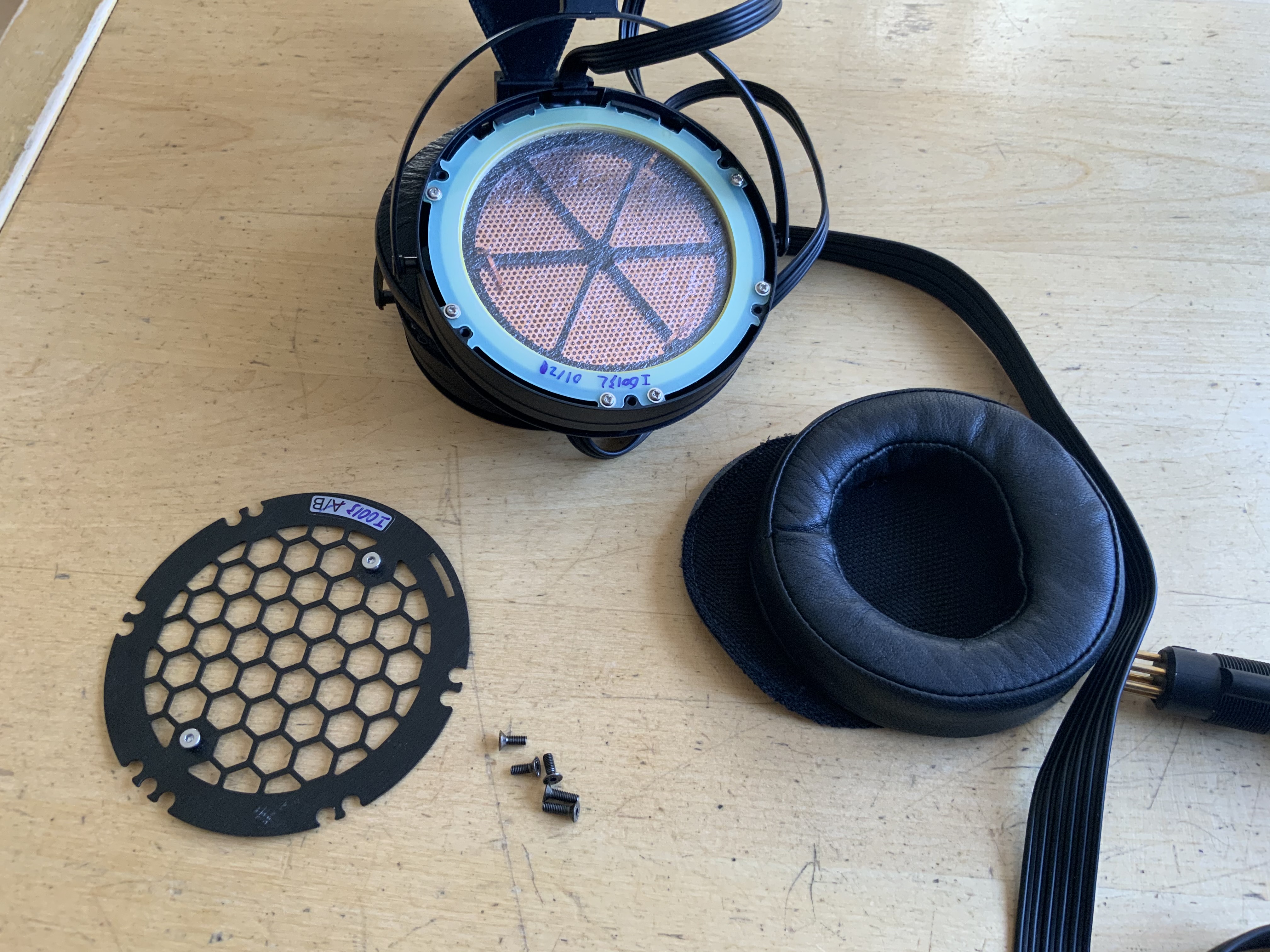
A small step towards a balanced Raal UberAmp setup. Completed a balanced smd (mostly) driver board today. Size 99mm x 35mm (3.9in x 1.4in). Two through hole unbalanced driver boards for comparison.
-
stax mafia circuit boards see updated links on page 5
JoaMat replied to kevin gilmore's topic in Do It Yourself
I have a reworked board layout of t2hvandlvpsukgsshv2 to a golden reference style T2 power supply. -
bdent.com has 83 pieces of 2sc3675. Grab them before they are gone.
-
Did some “google” and found a supplier in EU of Mogami W2534 with connectors. Advice most appreciated.
-
and now for something completely different part 3
JoaMat replied to kevin gilmore's topic in Do It Yourself
I’ve reduced power board voltages to +/-12 V. Two Mean Wells 12 V capable to deliver 29 A. Heat sink temperature decreased considerable – of course. My old ears think the sound is as good as with +/-24 V Next step is to make a few more boards to get a balanced set up. -
Happy New Year to You all!
-
I managed to get this working in Proteus. Headphone protector. A combination of Kevin’s comparator based protector and Stax delay circuit. Delay time set by C1/R8. LED D1 is blinking when relay is disengaged and steady when engaged. The screenshot shows U1 detecting an error – relay disengaged and LED is blinking…
-
and now for something completely different part 3
JoaMat replied to kevin gilmore's topic in Do It Yourself
Thanks for info, Kevin. Now changed driver voltage from +/-15 V to +/-35 V and op amp to OPA445 (from OP27). So far I’m happy with the outcome.


.jpg.ce6ff2751621b8626dbe1eb226ab30d7.jpg)
.jpg.b2f42eef882914cfd1b4eacbbda52e7b.jpg)
.jpg.8b8766d7314a3aa27ffdcfe1c6ba95a9.jpg)
