JoaMat
-
Posts
1,465 -
Joined
-
Last visited
-
Days Won
16


JoaMat's Achievements
Extra Special Silver Diner (5/6)
2.1k
Reputation
-
I have no boards left. Last pair sent to Finland some months ago. I’m working on an updated version of mini T2 boards. A senior Head Caser is test building - he has not approved the boards yet. I use a Gilmore DIY T2 PSU for all my electrostatic amplifiers including mini T2. But you probably want to use something more suitable. There are several PSU boards to choose from here https://drive.google.com/drive/folders/1r3g2TAtBUaBdiMorTWX7yYgeJ7maQbYW?usp=sharing .
-
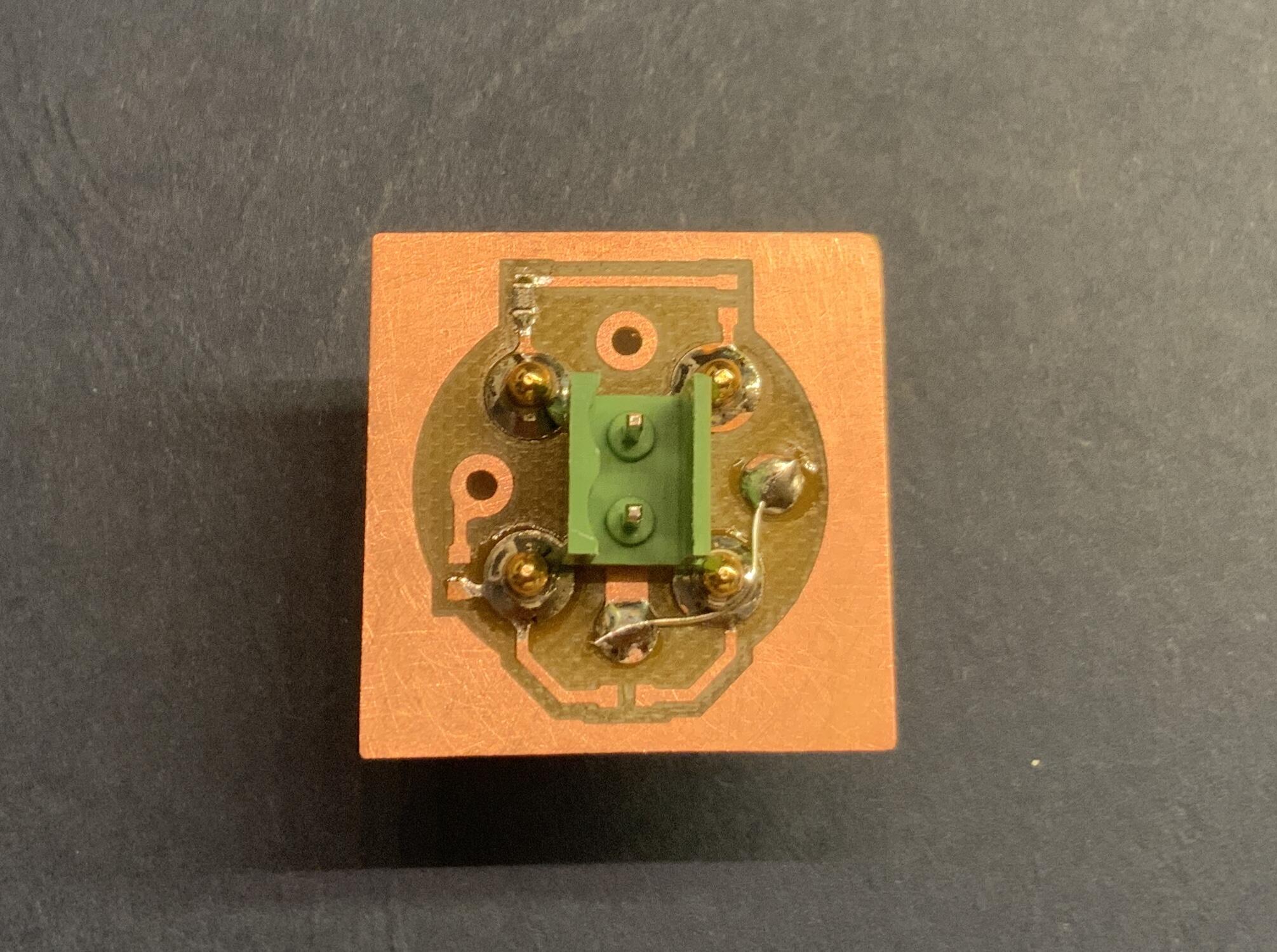
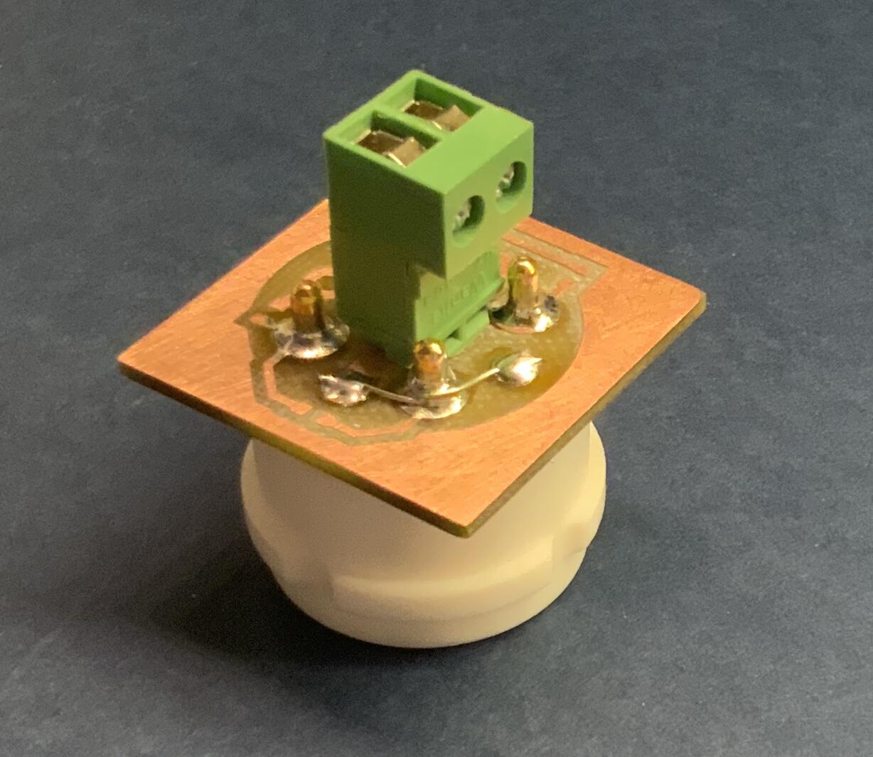
mini T2 ver.25 is starting to take its final shape, I think. I'm filing a little now and then. A small test board made now after coffee... here with UX4 socket. The connectors are from Electrokit https://www.electrokit.com/pcb-hane-5.08mm-2-pol-lagprofil and https://www.electrokit.com/skruvplint-pluggbar-5.08mm-2-pol-lagprofil. It is possible to use a regular 2-pole screw terminal, but I think the connectors in the pictures are much more practical. The circuit board connector in the pictures is notched in each lower corner with a sharply sharpened Japanese master chef's knife to fit between the solder islands. P.S. AI translated - I'm lazy

-
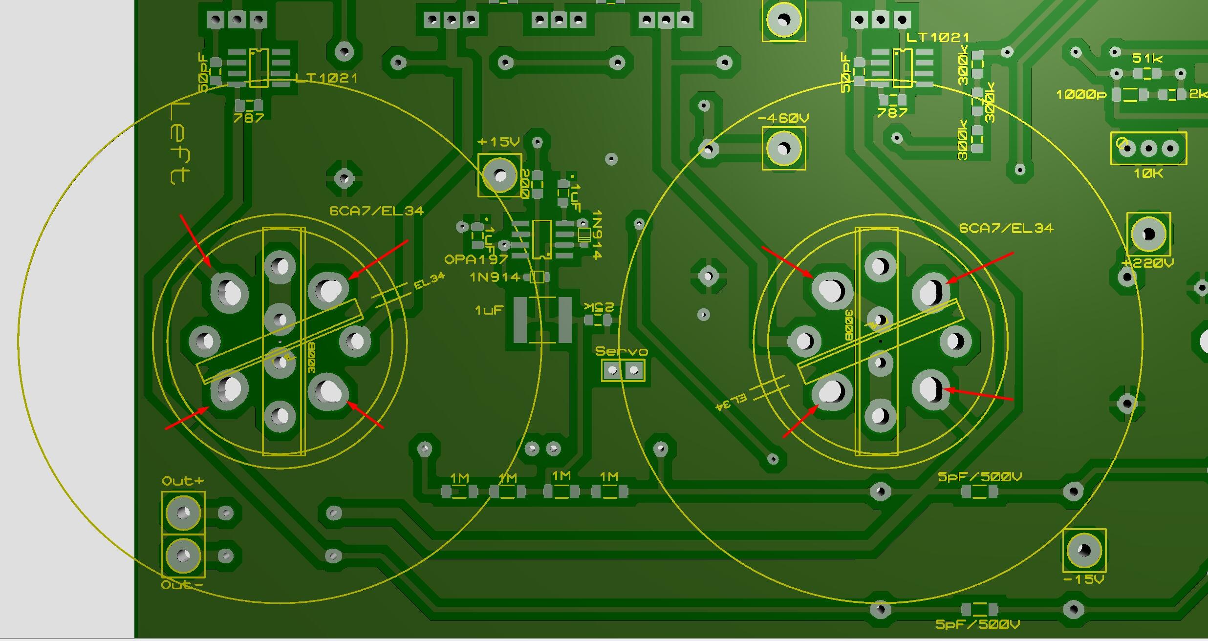
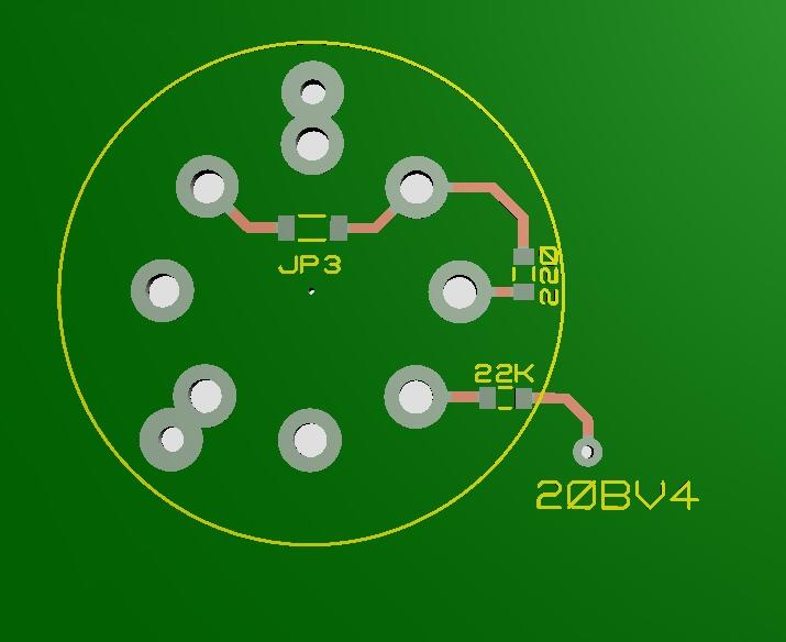
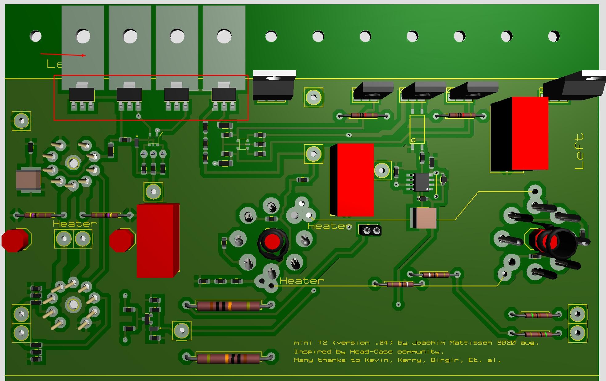
mini T2 board prepared for octal or UX4 sockets. Octal socket overlapped with UX4 (red arrows). If EML 20B-V4 or 300b/2A3 remove components at red arrows. If 300B/2A3 tie pads in green boxes together.
-
Welcome to HeadCase @EchoRoot Check below two links: https://drive.google.com/drive/folders/1r3g2TAtBUaBdiMorTWX7yYgeJ7maQbYW?usp=sharing https://drive.google.com/drive/folders/152thxfZafBmisG0CKCv6X82V-Ch9TjMH?usp=sharing
-
I believe you should move 22K resistor right tube to between G1 and 20BV4 pad. Then wire the 20BV4 pads together for bort EL34 and 20B-V4.
-
Yes. Upper left tube: from pin1 (G3) is a blue trace connecting Pin3 (A) - must be cut, but you probably have done that. Really an exciting project.
-
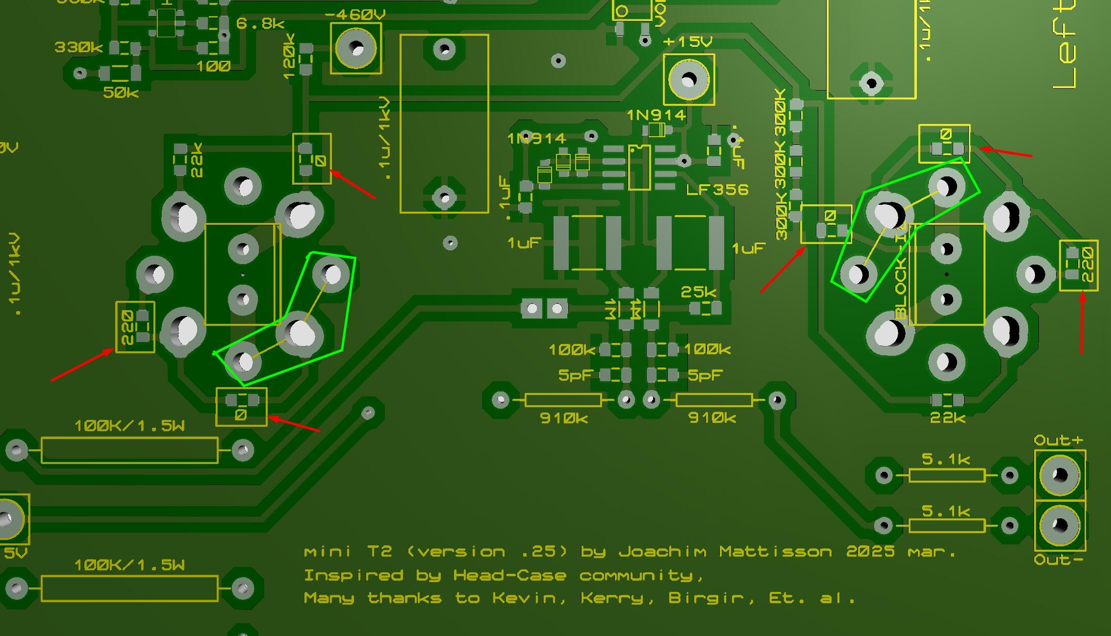
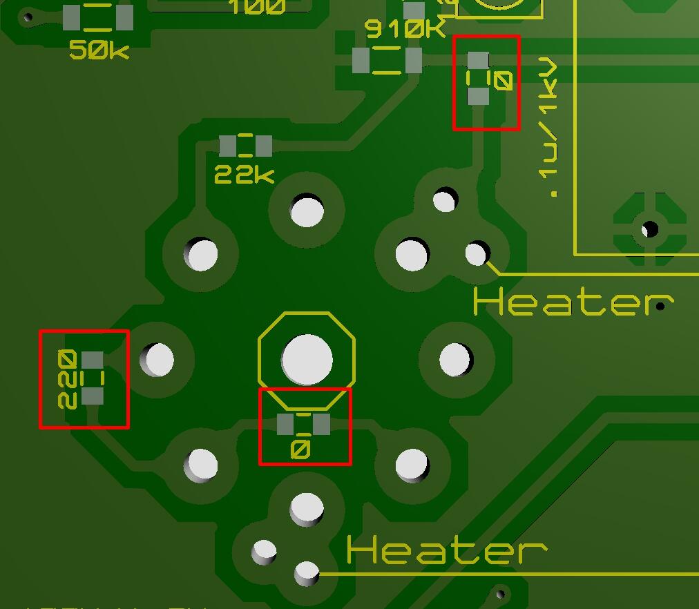
Done some more work. Added a couple of zero ohm resistors round the output tubes and a few other changes. If 20B-V4 tube remove the zero ohms and 220R resistors. Pcb layout is more fun than Sudoku.
-
Below is my way to describe how to prepare mini T2 for EML 20B-V4. Cut traces to Pin1 (G3). Cut traces at heater pins connected to resistor string 120K, 300K, 300K, 300K (one per channel). Purpose of the sting is to create -400V potential for Pin5 (G1) via 22K resistor. Remove 220R resistors. Remove 22K resistor Find a solution to put 22K resistors from Pin5 (G1) to resistor string between 120K and 300K resistors. This is probably the trickiest part. No heater wires between tubes of course. I’m sure you can modify your mini T2 to take the 20B-V4 tubes. But, maybe one should make a new board for the Emission Labs tubes… Not much heat produced by DC-DC converter supplies. No heat sinks needed.
-
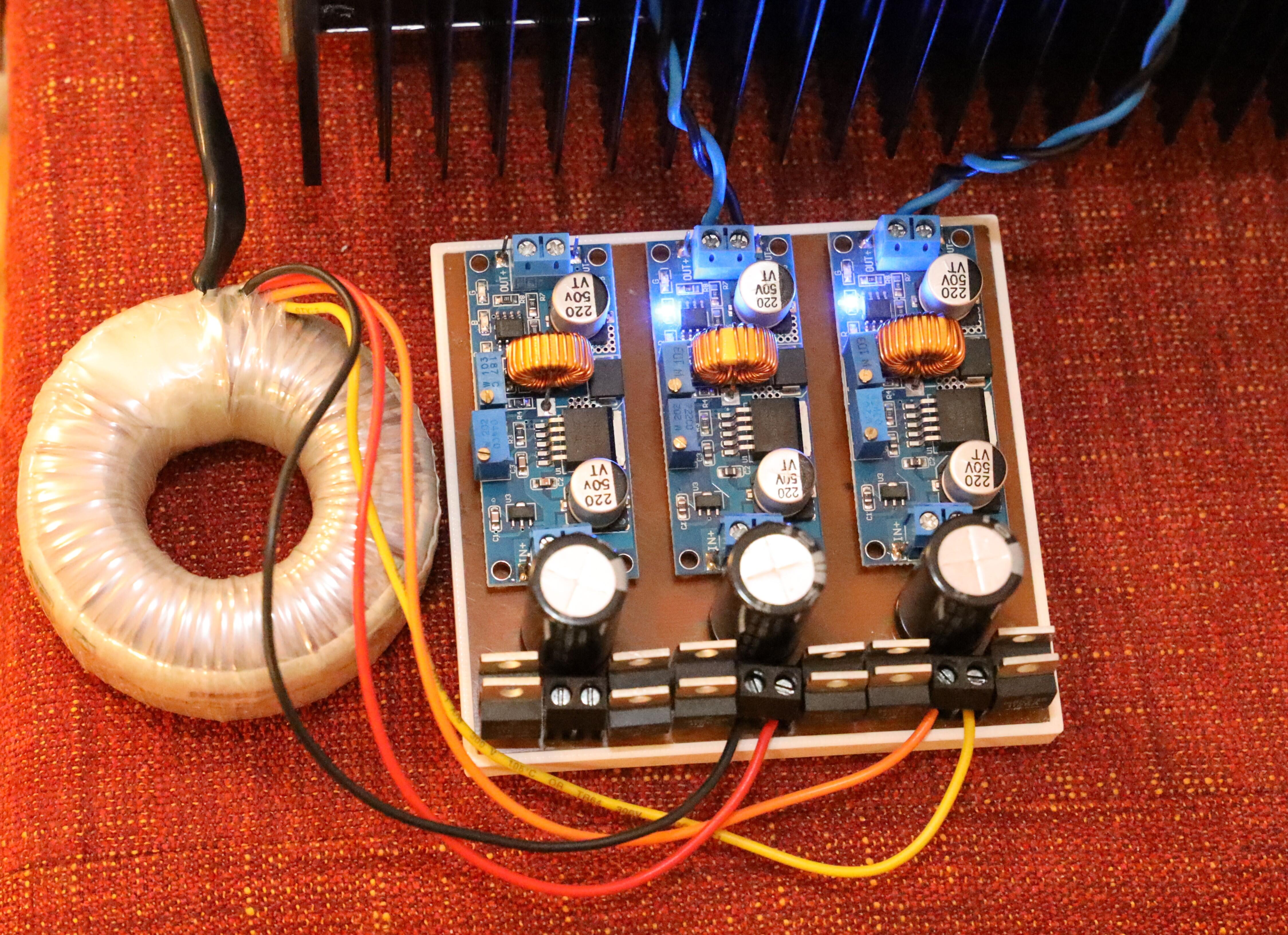
Tanks for the schematic. The DC-DC converter itself is 62mm x 26mm. Board with rectifiers, electrolytics and converter module is 91mm x 33mm per section. No changes to the circuit more than the tube change and its filament arrangement.
-
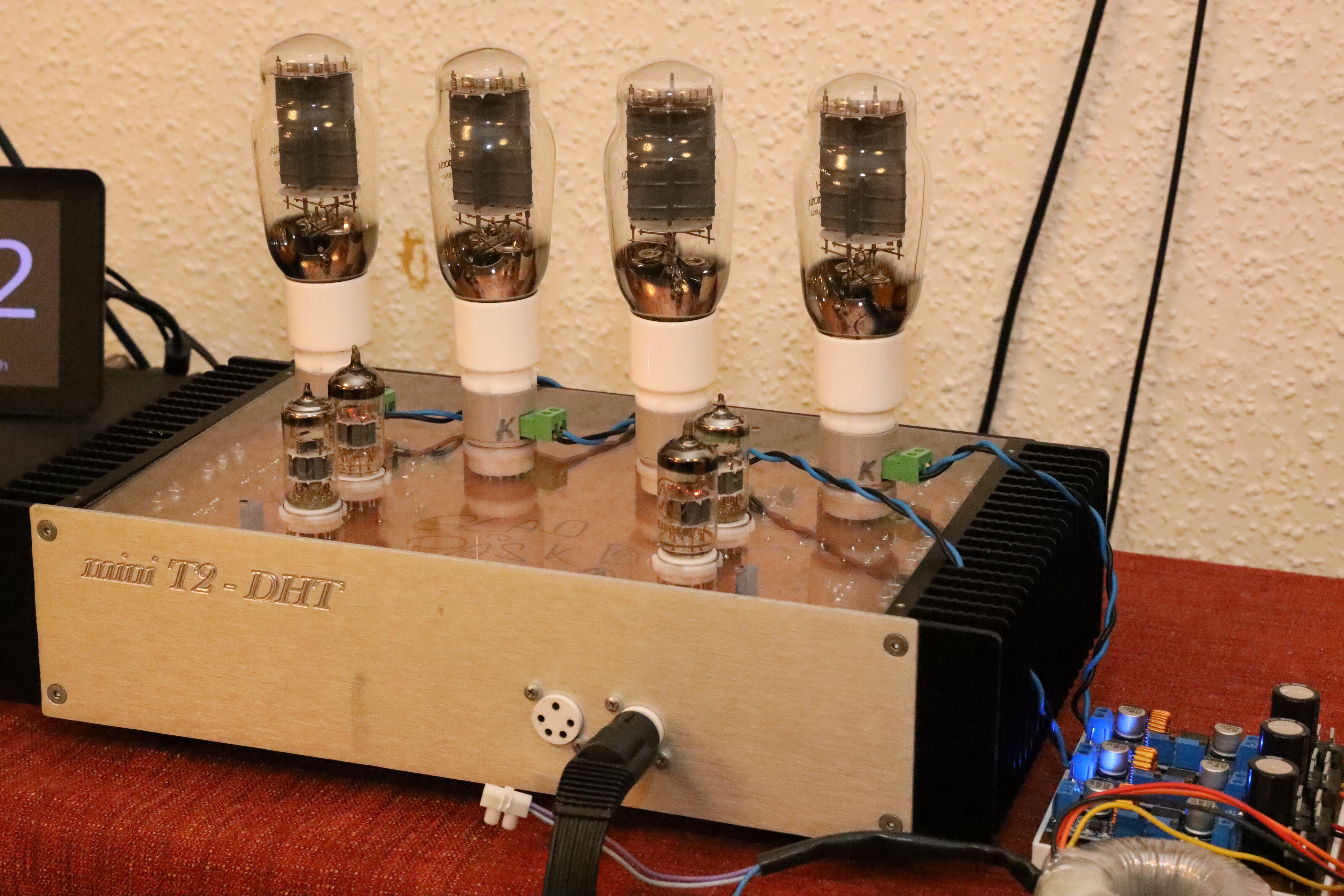
mini T2 DHT – for Emission Labs 20B-V4 tubes. Here with 2A3 and adapter from octal to 4-pin. The tube filament is injected to the adapter from 9VAC via rectifier and step-down DC-DC converter. Trimmers for voltage and current limit. I use it for 2.5V to 6.3V heaters.
-
Yes, a small problem with the 3D viewer... only a 1200 USD software. The LT1083 thing looks nice - is that your own design?
-
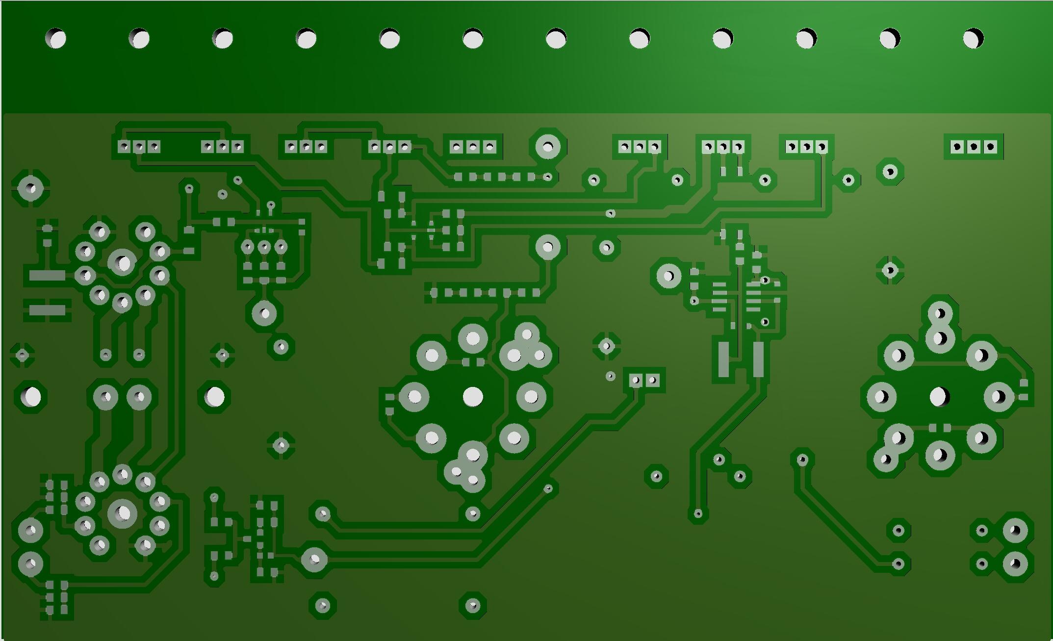
Glad you found a solution to the hum problem. I don’t have any empty board left – last one sent to Finland a week ago Below print screen from my PCB software, silk screen disabled, version .24.
-
I’ve had more than a couple of OPA197 failing. Original I used OP27 in offset servo position and they failed on a regular basis. OPA197 seems a bit more robust, but some casualties there too. When offset servo fails output voltages go high, almost all the way up to +HV (in my case anyway) and it has, so far, always been Op-amp problem. I’m working on a new version of a mini T2 board. STN9360 replacing KSA1156 and also moving offset servo up on tube side of the PCB – making it easier to replace a faulty OPA197. No problem with balance servo… knock on wood. Any ideas regarding a more reliable offset servo are more than welcome. Edit. I mixed up the balance and offset servos in the text above – now it’s correct.
-
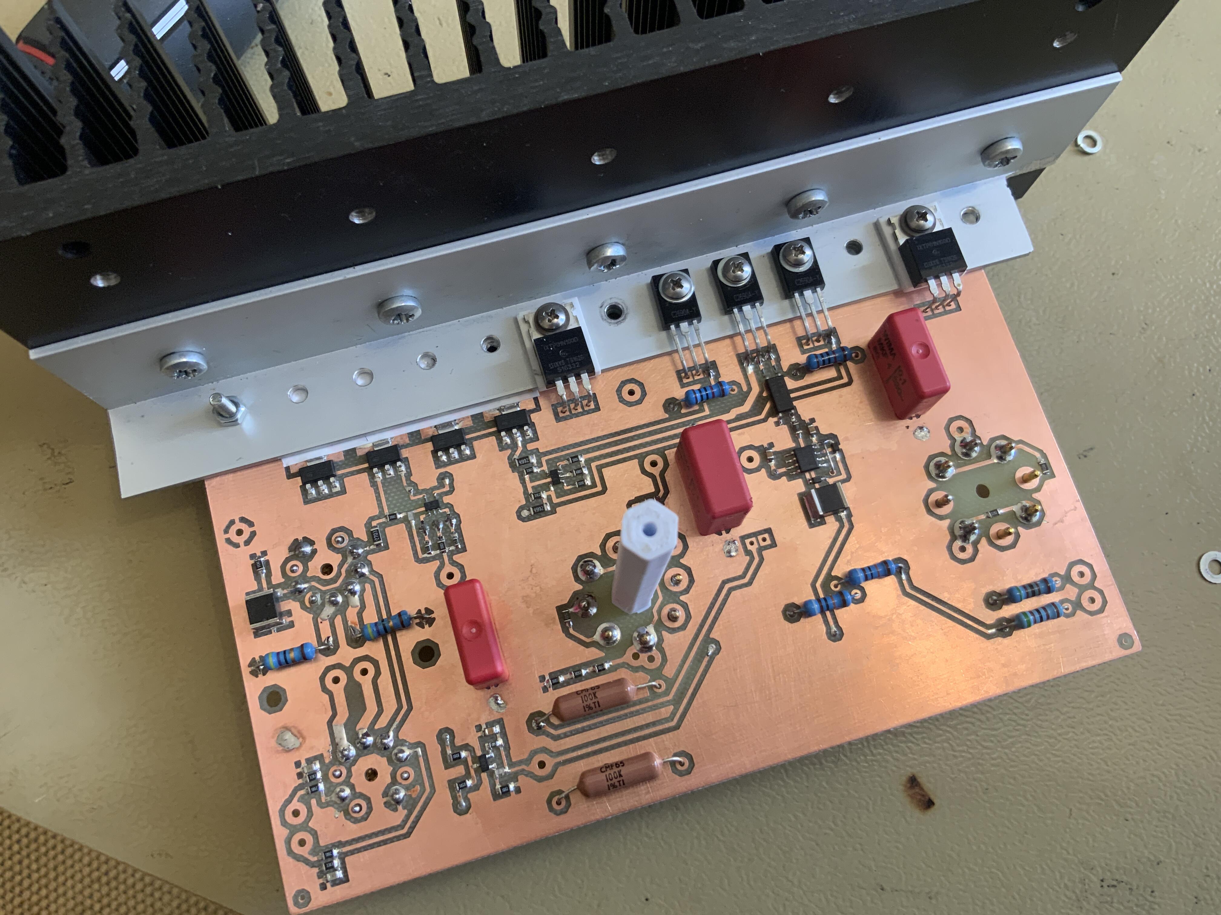
Sil-Pad 477-4862 under bracket at stn9360
-
There is about 1/4 W each KSA1156. Below STN9360 (in red) replaced A1156. Bare copper (no solder resist) under the bracket. Put thin Sil-Pad to isolate bracket from the copper. Time will tell… if this is a good idea. And 2SC3324 is now 2SC2713 on silk screen, Thank you.