


sbelyo
-
Posts
1,046 -
Joined
-
Last visited
-
Days Won
1
Content Type
Profiles
Forums
Events
Everything posted by sbelyo
-
Same here in Somerset county NJ. 18" and still falling. Snow blower is screaming for an overhaul but she blasted through it like a champ once warmed up
-
My wife constantly hounds me about moving somewhere warmer. I like the idea of not having to lift the windshield wipers every time it snows in winter. Basically we forget every time.
-
I only got 4-5" in central Jersey. But I managed to burry the snow blower in the back of the garage so I spent at least 30 min digging it out. Thankfully it fired right up
-

PC Board for Amveco PC mount low profile toroidial transformers
sbelyo replied to sbelyo's topic in Do It Yourself
looks dead on to me at first glance. I'll measure twice this weekend -
PC Board for Amveco PC mount low profile toroidial transformers
sbelyo replied to sbelyo's topic in Do It Yourself
Thanks, I'll take another look at it tonight -
PC Board for Amveco PC mount low profile toroidial transformers
sbelyo replied to sbelyo's topic in Do It Yourself
I did some measurements and it seems the center mounting hole needs to be centered. Other than that it's good. -
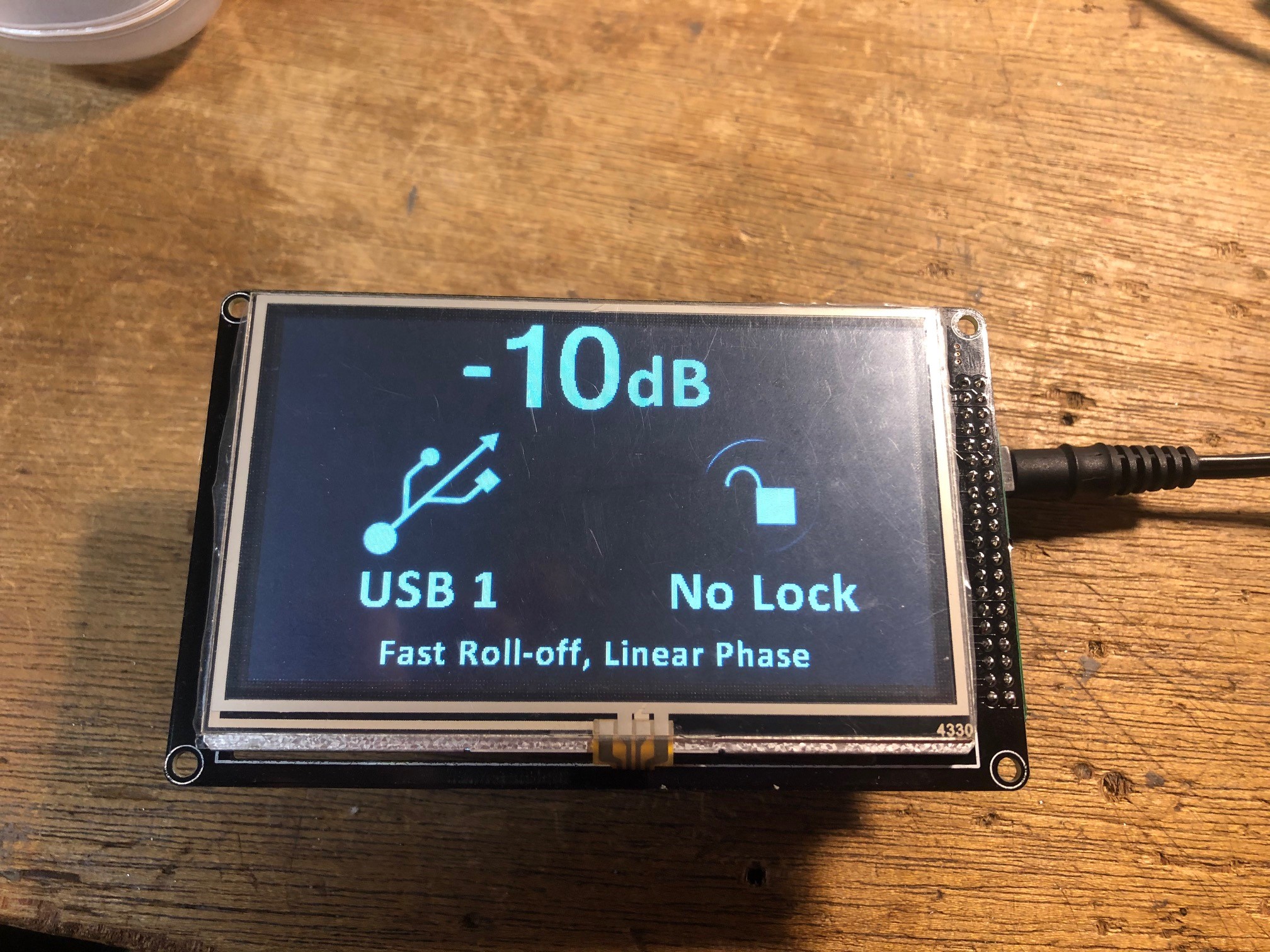
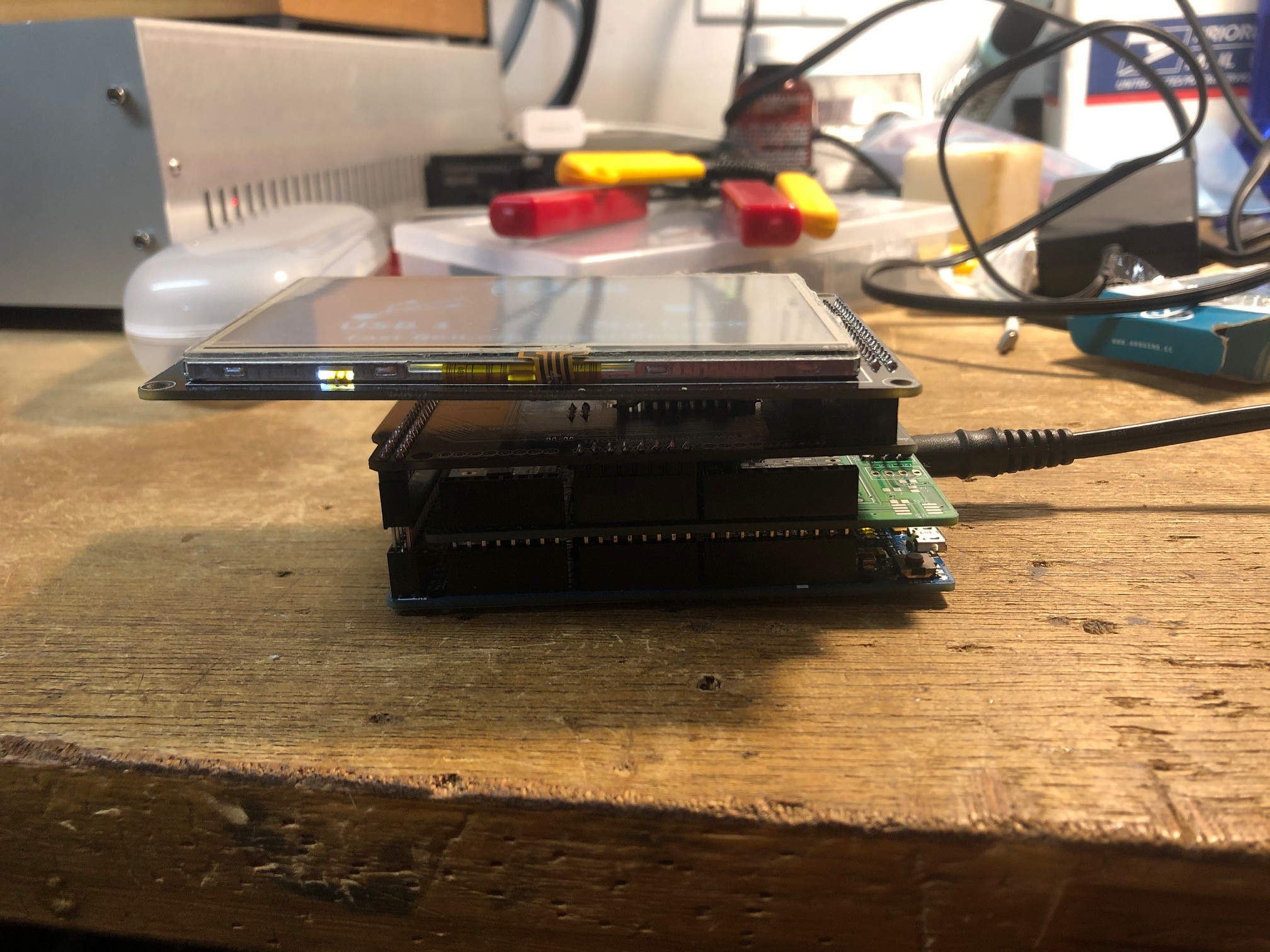
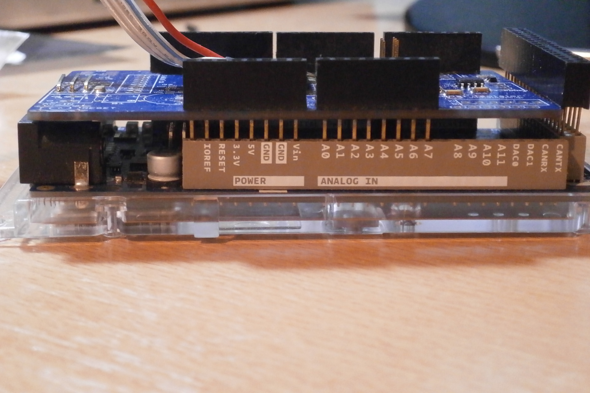
Finished my Arduino based DAC controller

-
here it is complete
-
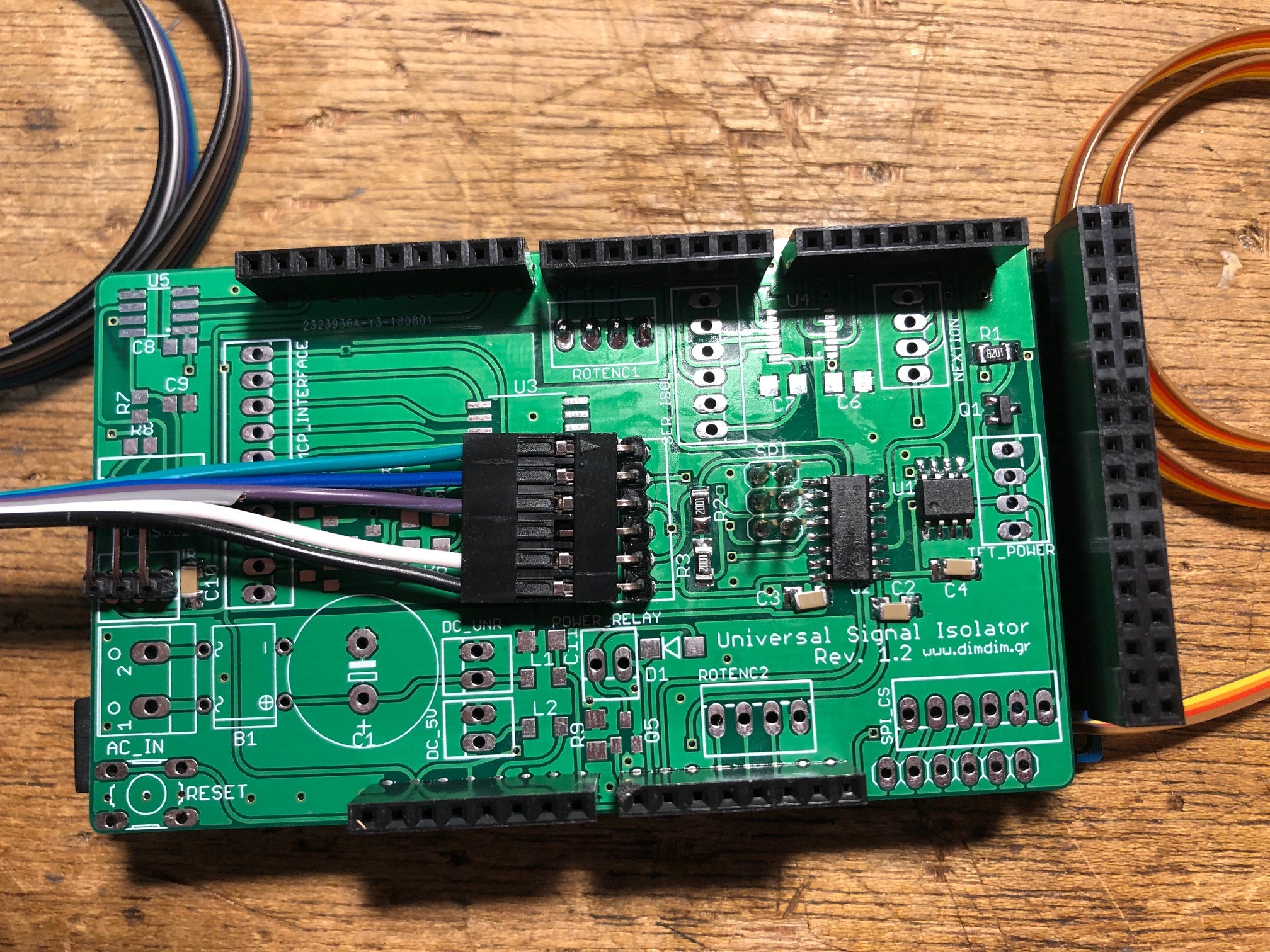
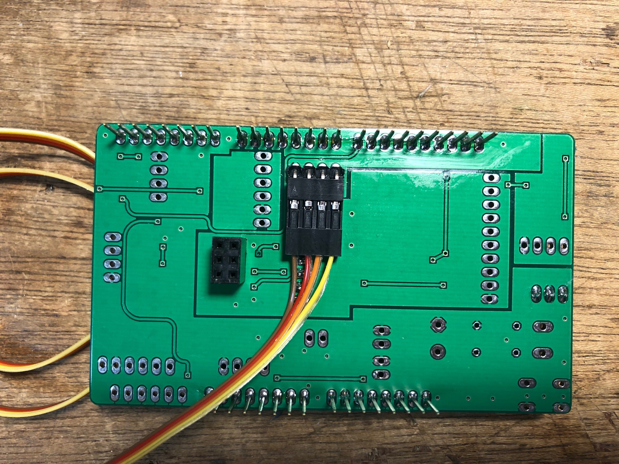
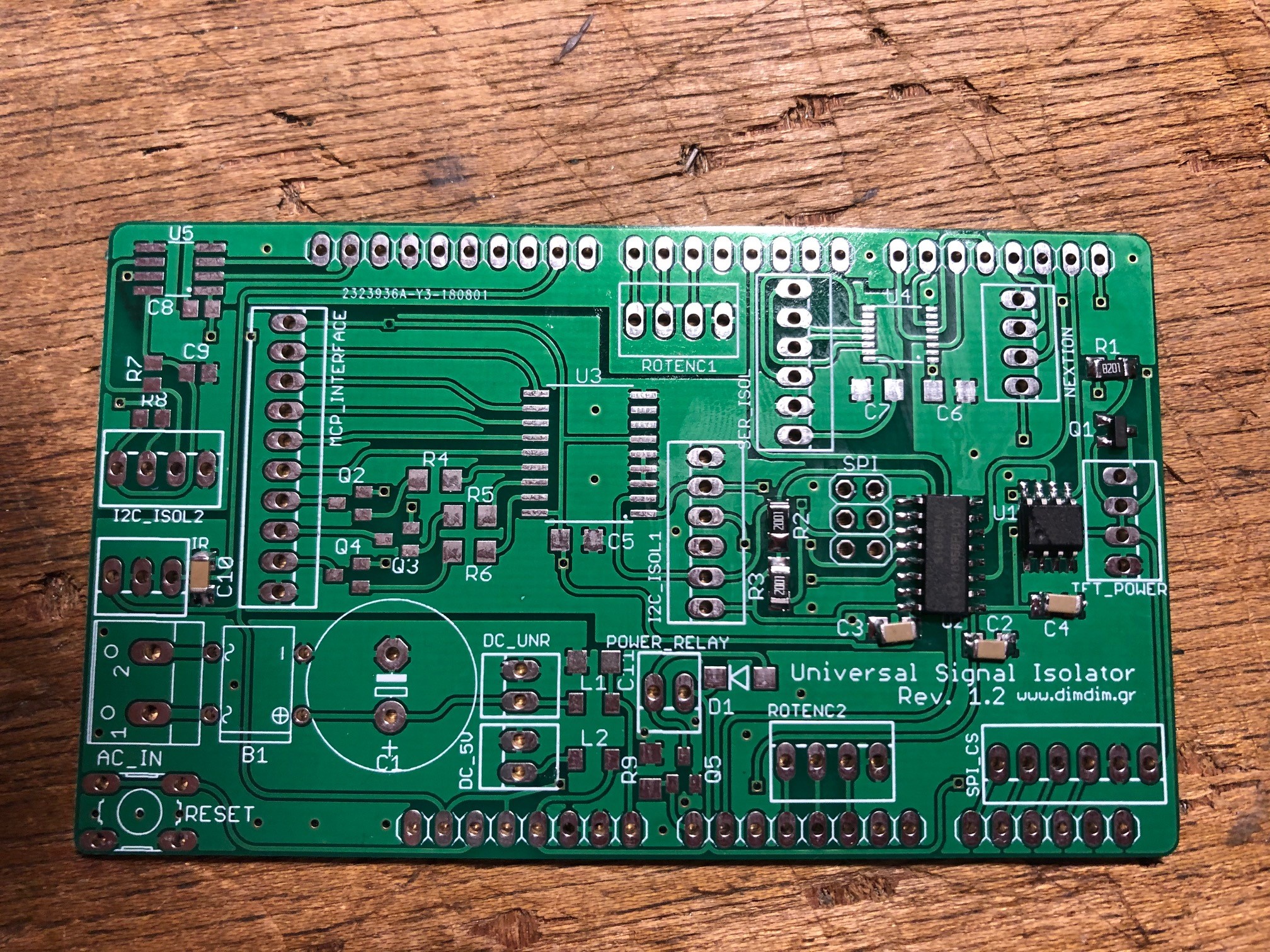
I soldered the surface mount components for a Universal Signal Isolator shield for the Arduino DUE. This will allow me to control my Buffalo DAC and add a TFT screen to it as well http://www.dimdim.gr/arduino/universal-signal-isolator-shield-for-the-arduino-due/
-
Need newb help with Arduino Due
sbelyo replied to sbelyo's topic in GoRedwings19's Computer Help Hotline
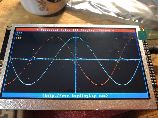
I got the no touch test pattern on the 5" display to work. For those that are new (myself included), here's what I did. Download the example file from buydisplay.com. Extract it and the copy the UTFT folder located in Libraries-Examples_ER-TFTM050-4\Libraries into the Libraries folder in the Arduino folder under My Documents (Windows). Open the .ino file located here Libraries-Examples_ER-TFTM050-4\Examples\No_Touch_GraphicTest compile and upload the code Remove the usb cable from the programming port Assemble the shield, screen, and arduino together Plug a 7-12 Vdc 1A or more power source into the power socket on the arduino board It should display the test
-
I'm looking to add an arduino to control my dac. I'm not worried so much about writing code as that's already done and proven to work for others. This whole platform is new to me. I can see that the initial scrpt or program is the .ino file and that will contain commands as well as references to libraries but I'm not sure how to put this altogether in Arduino IDE to upload it to the Arduino Due. I purchased this display for the project https://www.buydisplay.com/5-inch-tft-display-arduino-touch-shield-ssd1963-library-for-mega-due There is a download with examples in it here https://www.buydisplay.com/arduino/Libraries-Examples_ER-TFTM050-4.zip I want to test the 480x272 demo. I see the ino file and have downloaded the UTFT library and added it to Arduino IDE. Do I open the ino file in sketch then include the UTFT library and complile then upload? Or am I missing steps?
-
This was the best source for them for me https://www.amazon.com/gp/product/B0756KLNLX/ref=ppx_yo_dt_b_asin_title_o01_s01?ie=UTF8&psc=1
-
PC Board for Amveco PC mount low profile toroidial transformers
sbelyo replied to sbelyo's topic in Do It Yourself
Thanks... -
PC Board for Amveco PC mount low profile toroidial transformers
sbelyo replied to sbelyo's topic in Do It Yourself
Can anyone recommend a free gerber viewer that lets you print the layers true to size? Or at lease view them on screen where they're accurate enough for measurement. -
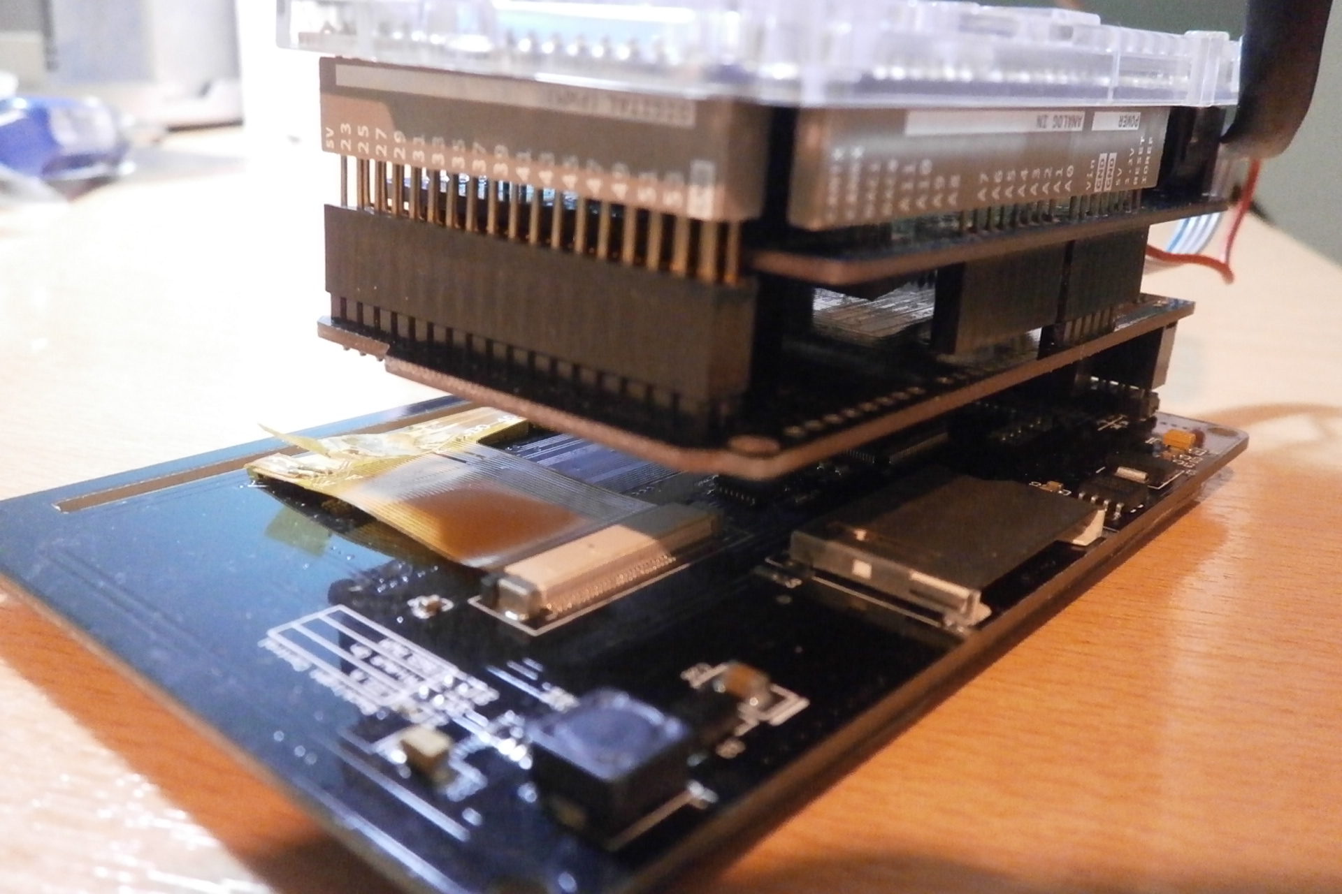
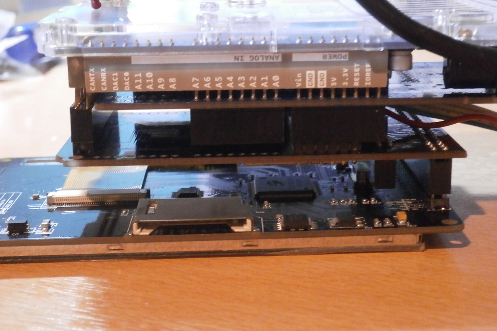
I need help finding board stacking headers like these. I need to stack a bunch of Arduino shields and a screen together. I can't seem to find them on mouser or digikey but thats probably me not putting in the right info
-
PC Board for Amveco PC mount low profile toroidial transformers
sbelyo replied to sbelyo's topic in Do It Yourself
At first glance and a quick measurement from the bottom, the hole seems to be dead center. I will print out the outlines this weekend and see where it matches up
-
I've done the same. But I totally get where purk is coming from.
-
All of my headphone's have been terminated or re-terminated with a 4 pin xlr for years now
-
PC Board for Amveco PC mount low profile toroidial transformers
sbelyo replied to sbelyo's topic in Do It Yourself
transformers should be here tomorrow -
PC Board for Amveco PC mount low profile toroidial transformers
sbelyo replied to sbelyo's topic in Do It Yourself
Max for length is 228.5 mm -
PC Board for Amveco PC mount low profile toroidial transformers
sbelyo replied to sbelyo's topic in Do It Yourself
For me it'd be cool to do the voltage switch. I have enough room for an IEC inlet with a fuse. Let me measure to see how long the board can be My only thinking was to have AC in on the left so the wires are very short to the front panel switch and then the secondaries are facing the AC in on the PSU boards. Basically just keeping the wiring as short and neat as possible. Is that creating more of a problem with noise the way it is? -
PC Board for Amveco PC mount low profile toroidial transformers
sbelyo replied to sbelyo's topic in Do It Yourself
That switch is cool, I like that -
PC Board for Amveco PC mount low profile toroidial transformers
sbelyo replied to sbelyo's topic in Do It Yourself
looks good. I expect the transformers next week so I'll measure that to check. Unless someone here has one -
PC Board for Amveco PC mount low profile toroidial transformers
sbelyo replied to sbelyo's topic in Do It Yourself
That would be cool... It looks like the outer holes are bigger so I think that's ok. -
PC Board for Amveco PC mount low profile toroidial transformers
sbelyo replied to sbelyo's topic in Do It Yourself
This look really good! I should have some 50VA coming next week. I don't have any 25VA, let me see if one is in stock

.jpg.515df83c8298d69867188424743a2a7d.jpg)