bobkatz
-
Posts
87 -
Joined
-
Last visited
Content Type
Profiles
Forums
Events
Everything posted by bobkatz
-
Building an energizer almost from scratch - advice on clamping zeners
bobkatz replied to bobkatz's topic in Do It Yourself
I can put a square wave into the transformer and see what level trips the Zener and how quickly. And the effect on the system. Given that it's the high impedance winding, even if i don't put in a resistor, it would seem to me a kind of current limiter.... just a thought, not my field of expertise. -
Building an energizer almost from scratch - advice on clamping zeners
bobkatz replied to bobkatz's topic in Do It Yourself
I pulled the DC-DC converter from the Topping board to measure it and see if it's worth keeping for some purpose. It's an unmarked black potted module. Output voltage is somewhat proportional to input. It normally receives +15 VDC from the motherboard. I fed 15 VDC into the converter and got 591 volts out, no load. Unfortunately, the higher the input voltage, the worse the AC voltage (output noise or ripple) as measured on my Fluke 289. At 15 volts in, 591 volts out, the fluke shows a horrid 2 VAC. Without scoping it I can't tell you what kind of noise that is, but for me that's cause for concern. Bob -
Thanks, Kevin. Yes, it is positive voltage input. It's hard to tell, but I think the output polarity follows the input polarity. It's good to hear your advice and I'm very glad that it matches what I received from another expert. 🙂 I will ground the center taps to chassis AND to audio input ground. Please see the thread on the Topping amp for what I discovered about its onboard DC-DC converter.
-
Well, I found an app note from Spellman High Voltage, that makes the Bertan supply. Looks like Grounding is a VERY Good idea: How should I ground your supply? Grounding is critical to proper power supply operation. The ground connection establishes a known reference potential that becomes a baseline for all other measurements. It is important that grounds in a system are low impedance, and are connected in such a way that if currents flow through ground conductors they do not create voltage level changes from one part of the system to another. The best way to minimize the possibility of creating voltage differences in your system grounding is to use ground planes via chassis and frame connections. Since the source of the high voltage current is the power supply, it is recommended that it be the tie point for system grounds to other external devices. The rear panel of the power supply should be connected to this system ground in the most direct, stout manner possible, using the heaviest gauge wire available, connected in a secure and durable manner. This ties the chassis of the supply to a known reference potential. It is important to understand most damage to HV power supplies occur during load arcing events. Arcing produces very high transient currents that can damage power supply control circuitry (and other system circuitry) if grounding is not done properly. The product manual provides more detailed information regarding grounding requirements. If you have any additional questions, please contact the Sales Department.
-
For the bias voltage, I will be using a DC power supply I'm getting from Ebay: Bertan PMT-10C/N -1 kV 4mA Adjustable High Voltage DC Power Supply. Even though this supply takes in a DC input, the spec sheet says: "These fully enclosed modules are specifically designed with proprietary linear power conversion techniques to provide exceptionally low ripple and noise" Not sure how they can get a regulated high voltage from +24 VDC using "linear techniques", but in without using a switcher, but anyway, my question is: Is it necessary to ground one side of the bias supply? That is, connect it to chassis, U ground and audio ground? Is it necessary or useful for one side of the bias supply to be connected to the same ground as the source audio power? What do you think ? Also, I should measure and see if the Bertan's output is galvanically isolated from its input and maybe ask the company if it's even ok to ground one terminal of its output.
-
Building an energizer almost from scratch - advice on clamping zeners
bobkatz replied to bobkatz's topic in Do It Yourself
Is using like a 2.5 kohm in series with each leg to the phones a bad idea? Is it inviting high frequency losses? Instead of feeding the transformer directly to the connector pins? -
Building an energizer almost from scratch - advice on clamping zeners
bobkatz replied to bobkatz's topic in Do It Yourself
Limiting the amp's power? That's a double edged sword! My instincts say that limiting the power rail just means the amp is going to clip earlier and to my ears, the closer you let an amp get to clipping, the harsher it can sound. So I'd like to keep the amp well below its clipping point. Now it seems to me if you put a current limiting resistor, like a 5k, or two 2.5K on each audio leg, in series with the leads to the phones, then the zener after that won't be shorting the amp and transformer when it clamps with an overvoltage. But I can do a sort of protection by carefully adjusting the analog gain structure of my chain post DAC so that maximum analog level (top of the analog volume control) at 0 dBFS (maximum digital peak level) will produce no higher than 700 Volts RMS at the secondary. First of all, that would be very loud and my analog gain would normally be well below that. So I would view the zener approach as just an emergency clamper, a protection from unforseen circumstances. How does that sound? -
Building an energizer almost from scratch - advice on clamping zeners
bobkatz replied to bobkatz's topic in Do It Yourself
OK, I think I found the zeners, it would be wonderful if you would check my idea: 1) Protect Bias supply from over voltage. A single Vishay 1N5061, 600 volt avalanche diode. The supply I bought on Ebay is a DC-DC converter, Bertan, adjustable high voltage power supply, up to 1 kv at 4 ma. Takes in +24 volt. So it would seem a good idea to put the zener across its output. 2) Protect the headphones. How about a pair of 800 volt Vishay 1N5062. What do you think? -
Building an energizer almost from scratch - advice on clamping zeners
bobkatz replied to bobkatz's topic in Do It Yourself
Thanks. That's what I was afraid of. Keep in mind that the intermodulation distortion I saw in the Topping amp concerns me. I think that's the amp module, not the transformer as I don't think IM is a typical component of a transformer. If the TPA amp sounds and performs like crap I'm only out $10 each and I'll seek another solution. I'm thinking an alternate amp solution that I can handle and implement conceptually is a +-24 volt power supply with a pair of 990-style opamps in push pull. A 990 can deliver 13.8 volts RMS into 75 ohms so it's a pretty powerful discrete opamp. I found a 33:1 transformer so basically if I want to get to max of 600+ Volts RMS/sine wave I need nominally up to, say 19 volts RMS in. That's 19.8 volts in push pull. And as you all know, push-pull helps cancel even order harmonics, which could help the purity of tone. Again, if I don't like the 990 approach, I'll try something different until I'm happy with the sound 🙂 Back to the clamping zeners. Does anyone have a value recommendation and a simple orientation schematic? Thanks! -
Building an energizer almost from scratch - advice on clamping zeners
bobkatz replied to bobkatz's topic in Do It Yourself
I know. I have experience with Lundahl in another application. But I do have a source for another extraordinary transformer that I can afford that i hope will work very well. We shall see. -
Background: Just for fun, I'm going to build an energizer using a small Class-D power amplifier and a transformer. The inspiration was that I'm basically junking my recently-purchased and rejected Topping EHA5 and O can use the chassis and connectors. The rest I plan to junk. I bought a high voltage DC-DC converter for the bias voltage and a pair of toroidal transformers meant for a tube amplifier. The transformers are so big I may have to mount them on top of the Topping Chassis! For the amp I'm hoping that the Texas instruments TPA3116d2 Class D chip will do a good job. If I don't like the soun of this chip, I'm only out $10 for a populated board from Amazon!!! OK, if anyone can help, please, I'd like some advice on clamping Zeners for driver protection. Cribbing from a Stax SRD-7 schematic I see ZL01 through ZL04 but it doesn't give the values or the orientation of the Zeners. If possible, it would be nice to pick a value that will protect the headphone but have no sonic effect on headroom or impact. Many thanks in advance for any advice!
-
I'm sorry that the BBS interface does not show the names of the files. The unlabeled ones are square waves at 1 kHz, 10 kHz, 20 Hz, 100 Hz. Next time I upload I'll annotate all files in the GUI 🙂
-
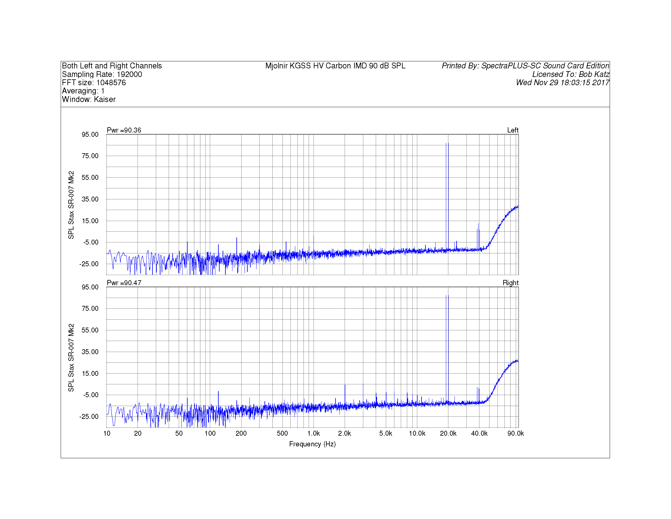
My pleasure! Just uploaded the Mjolnir measurement. Put the Mjolnir and Topping pictures side by side!
-
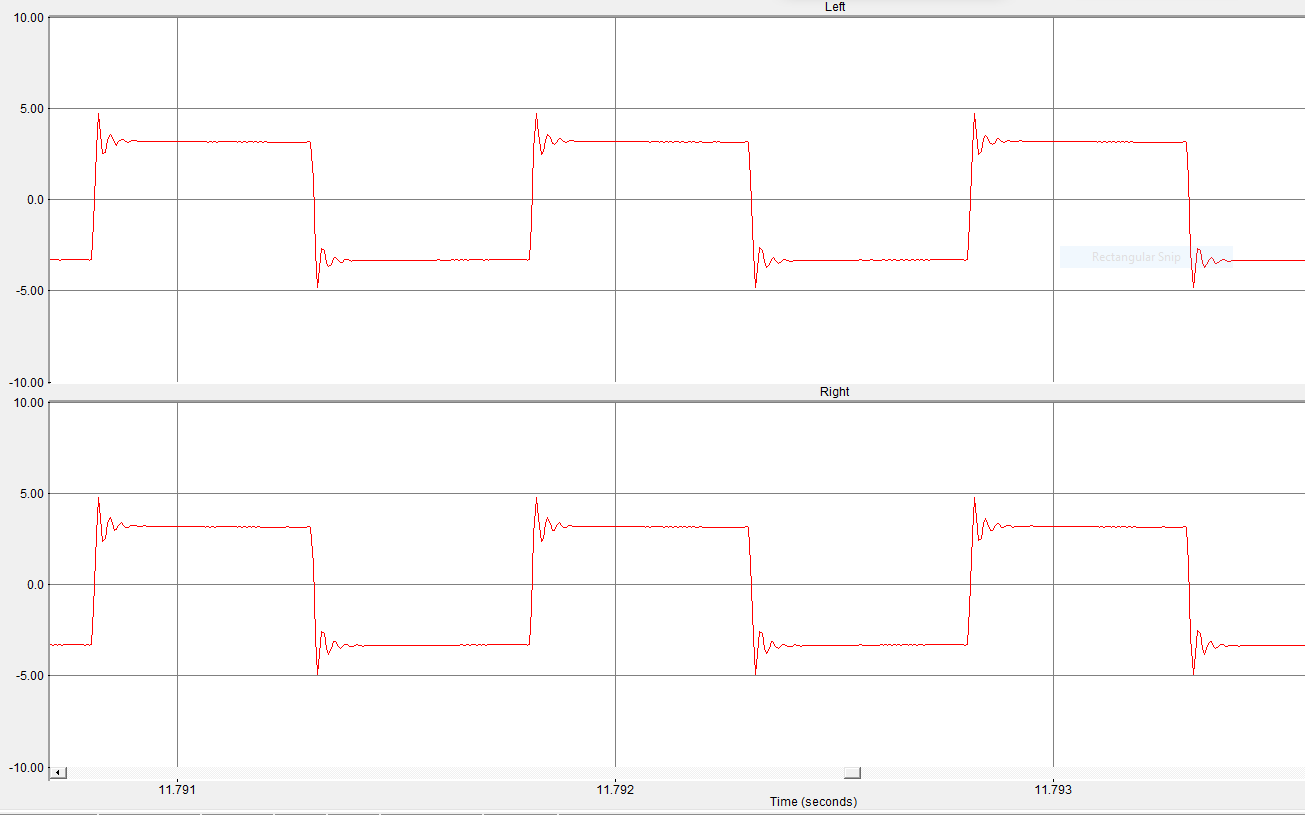
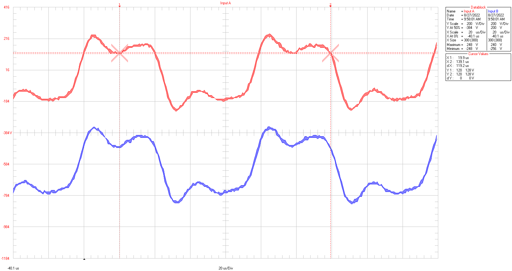
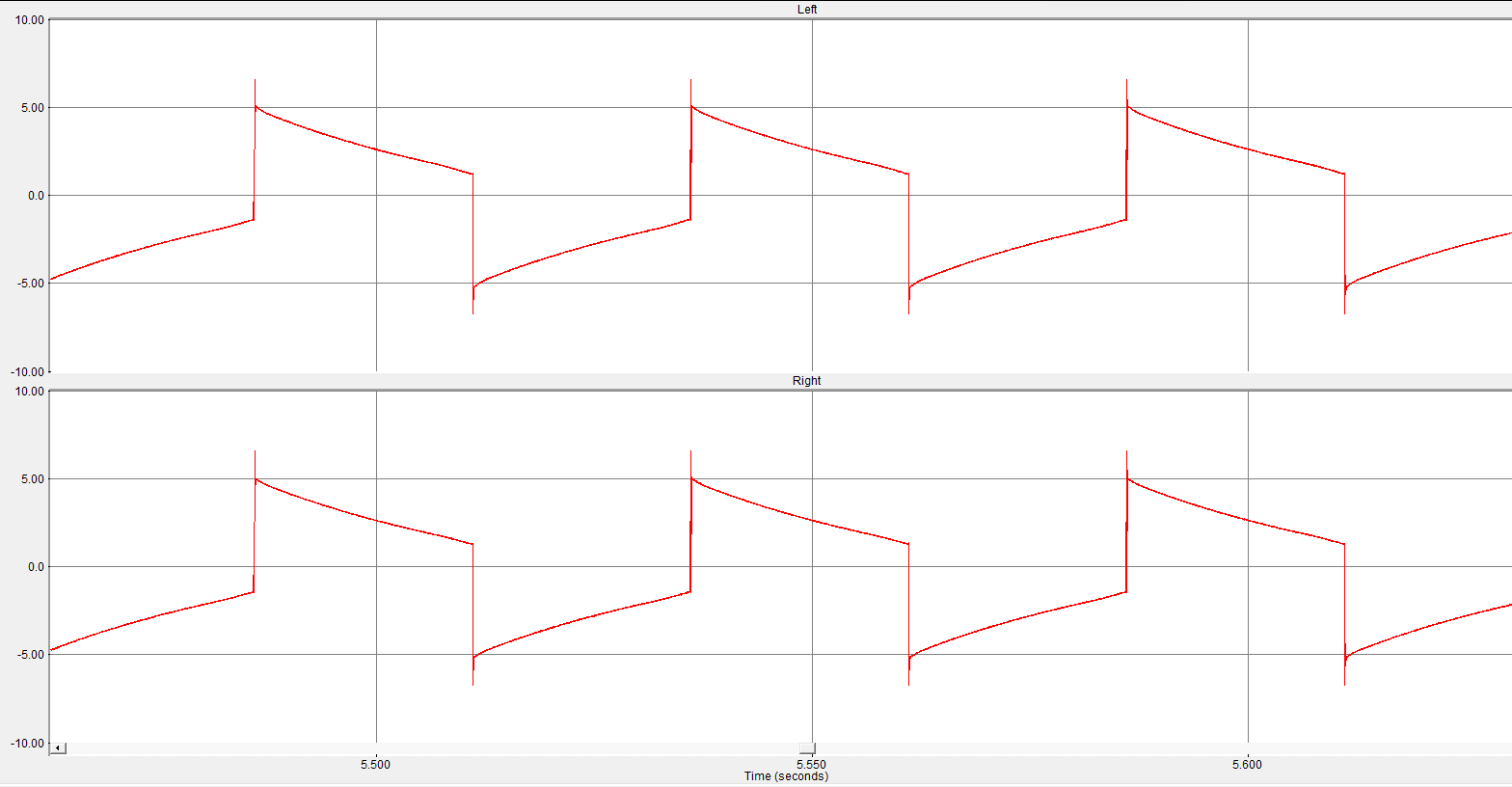
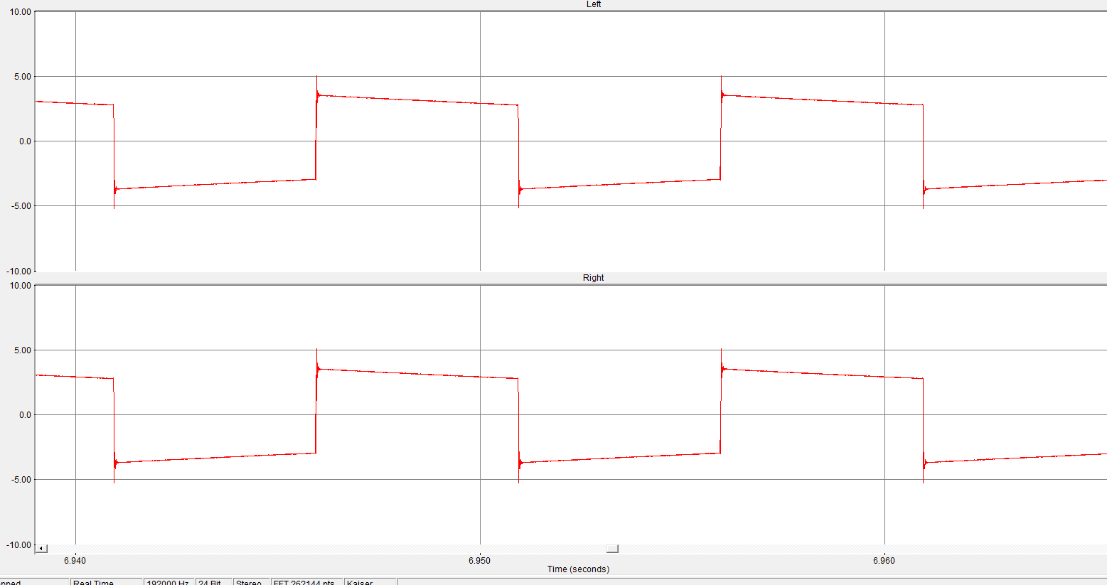
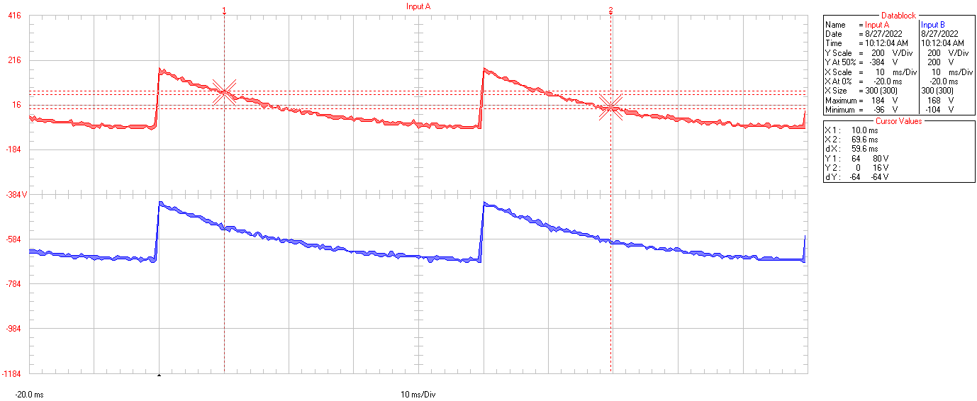
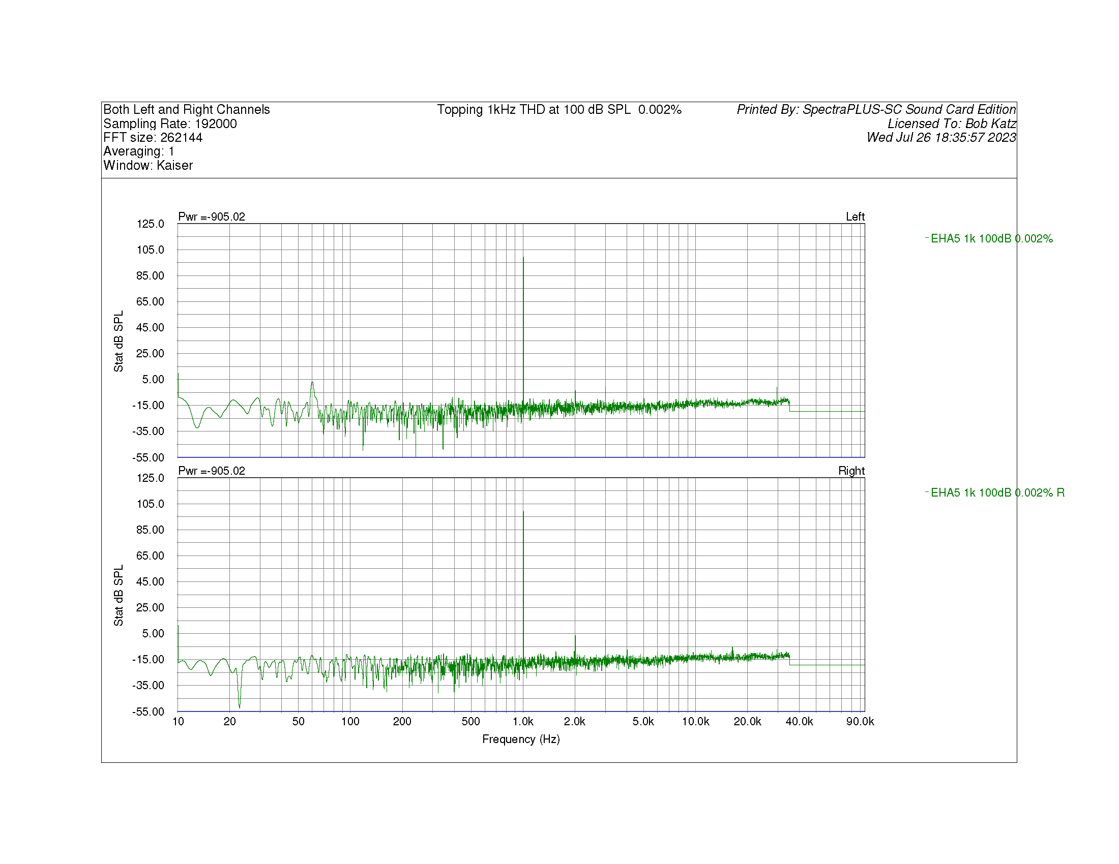
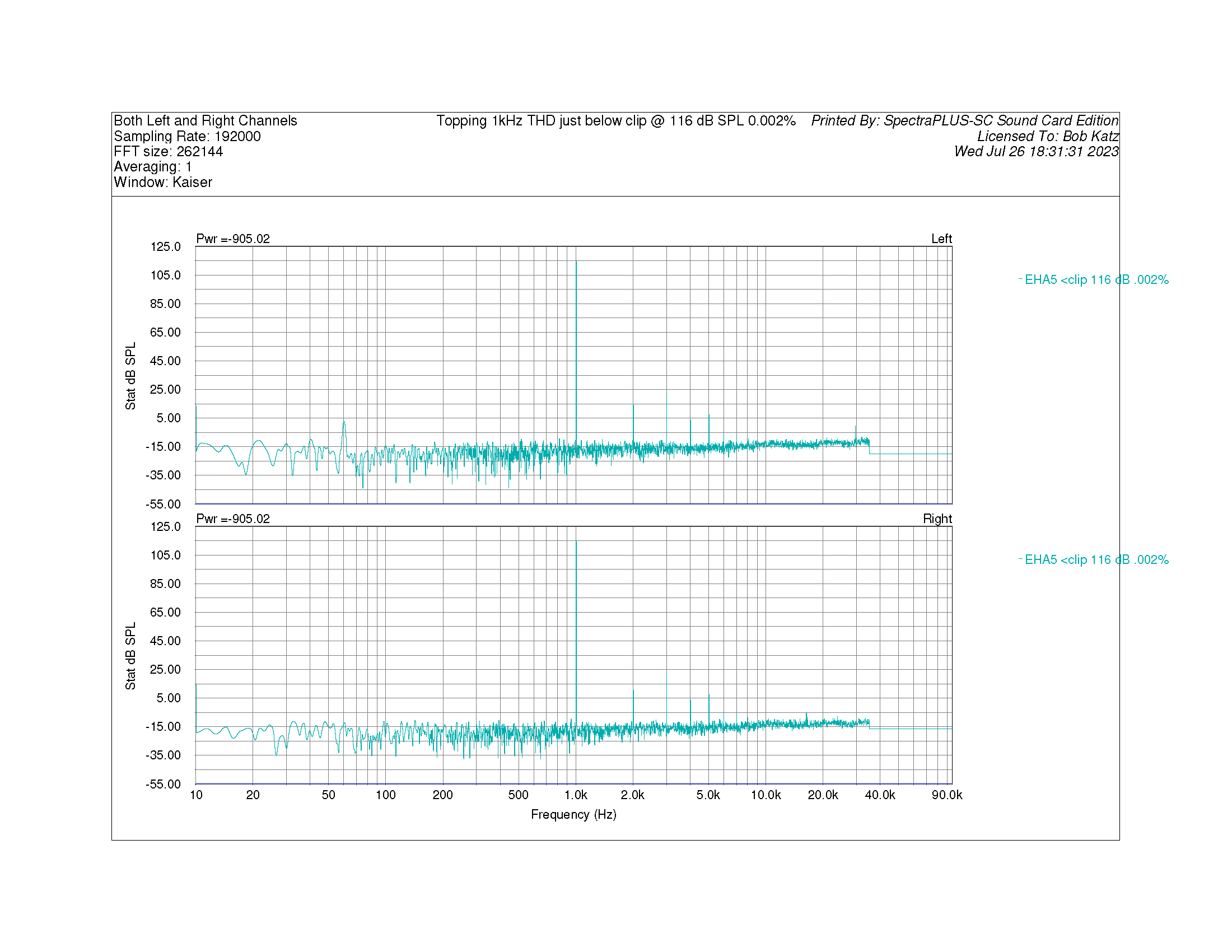
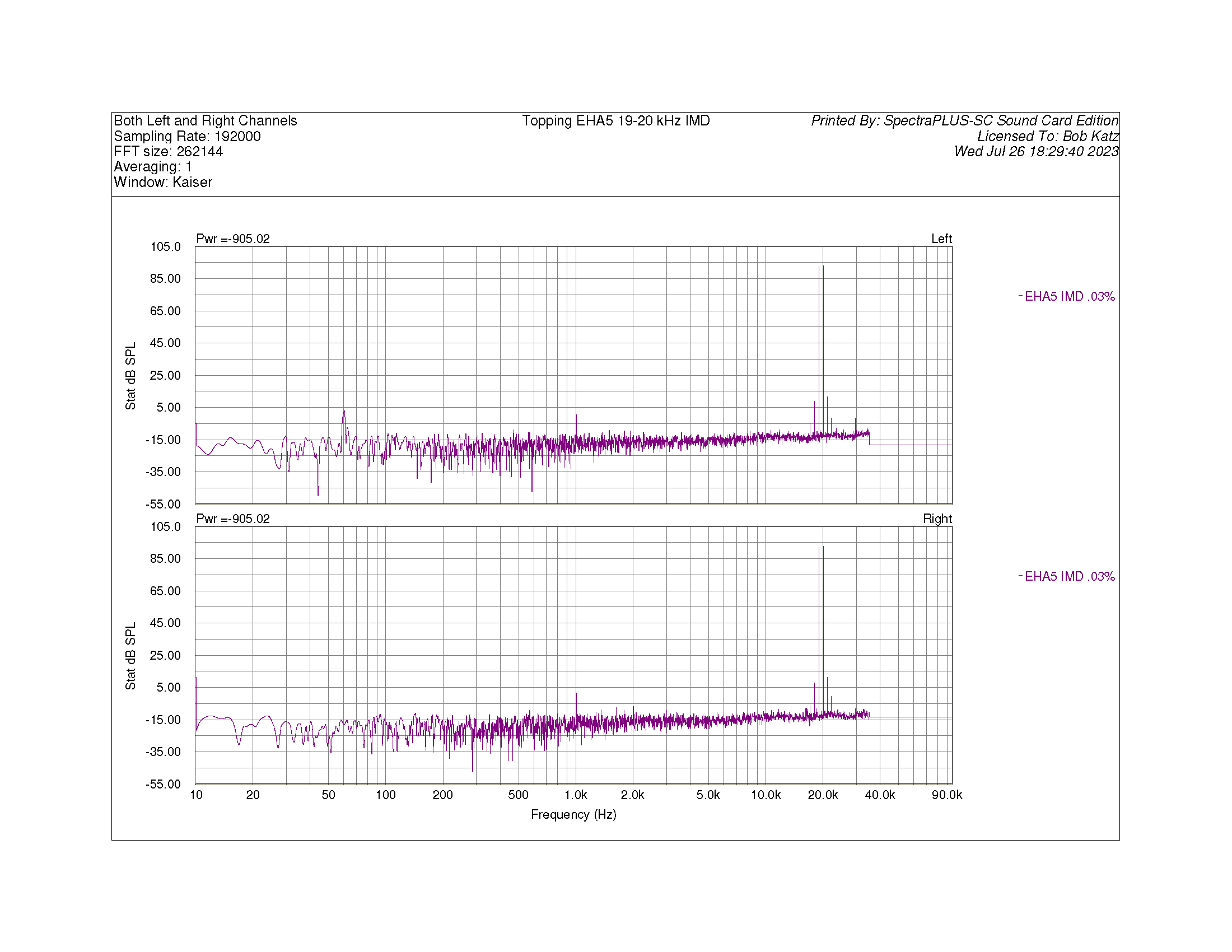
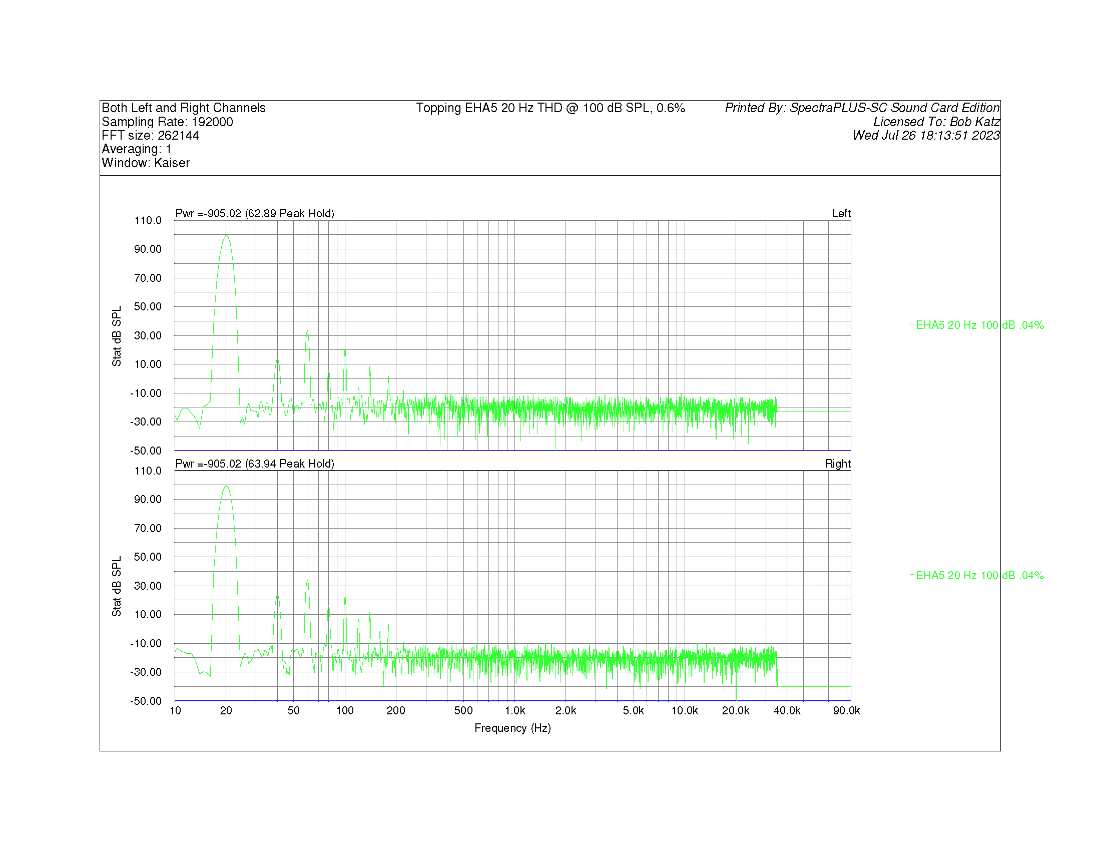
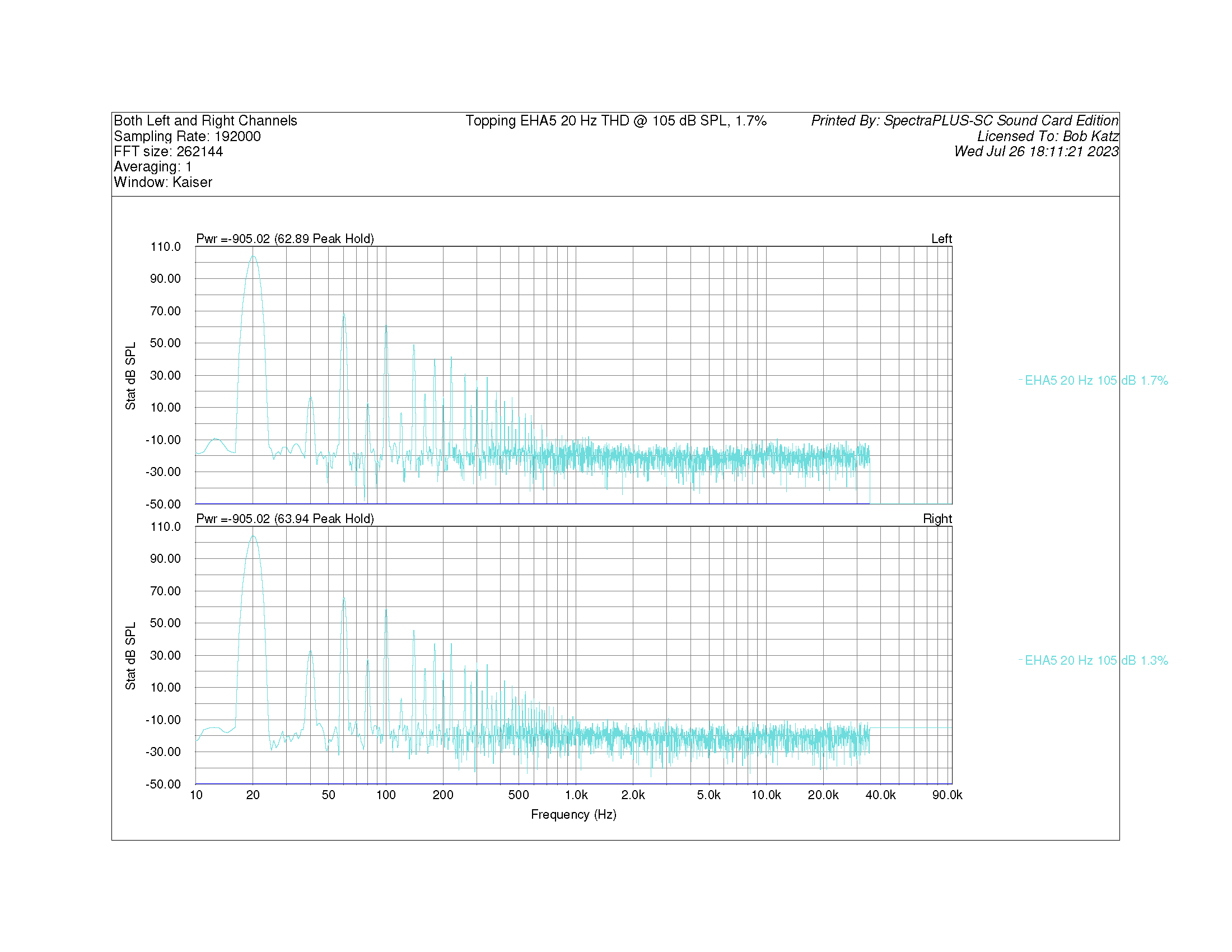
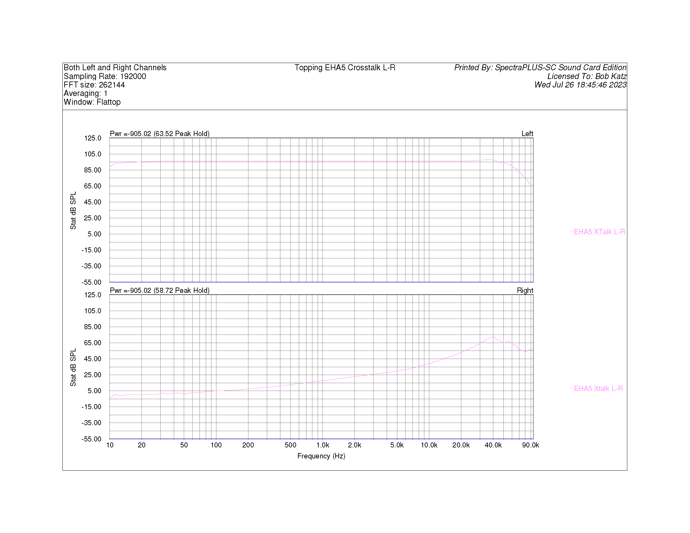
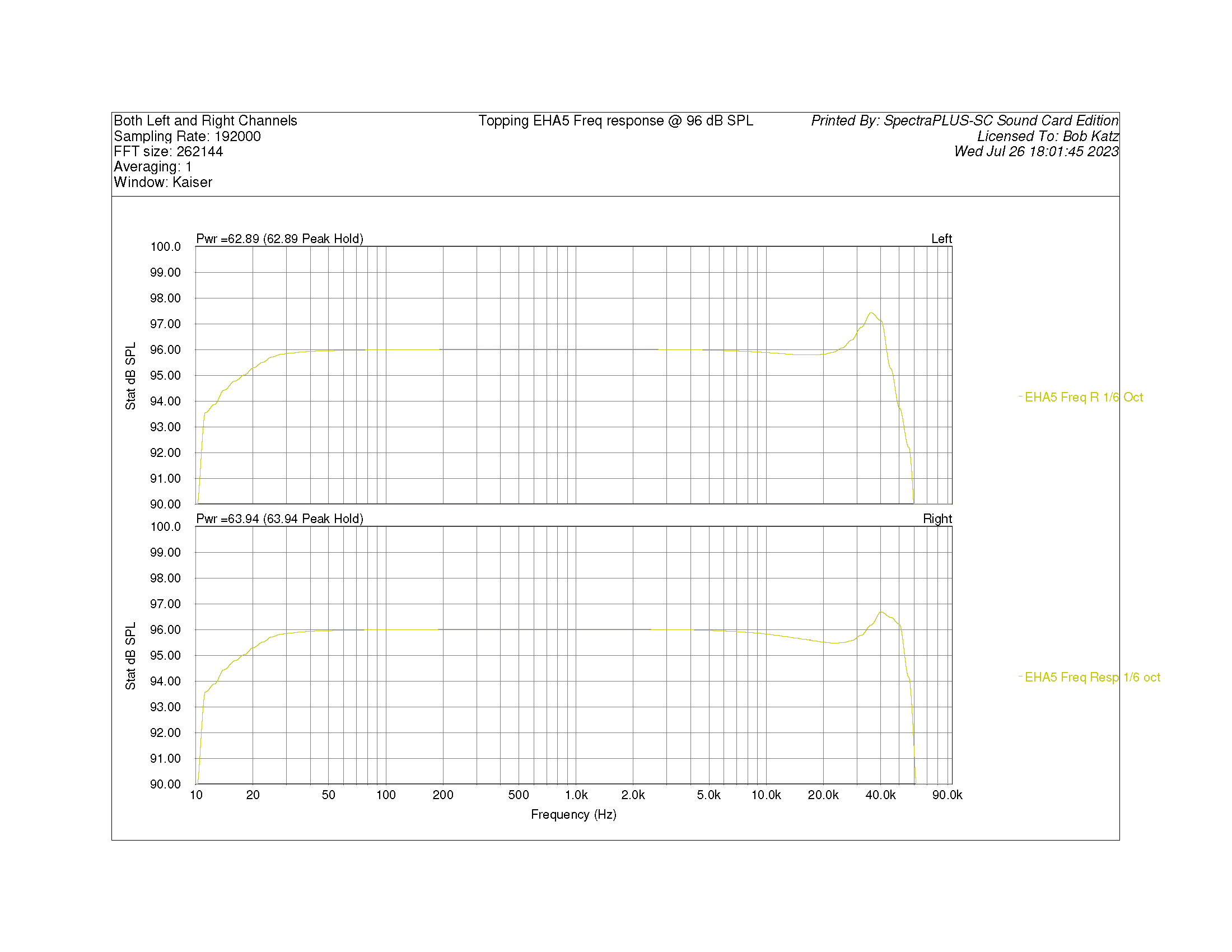
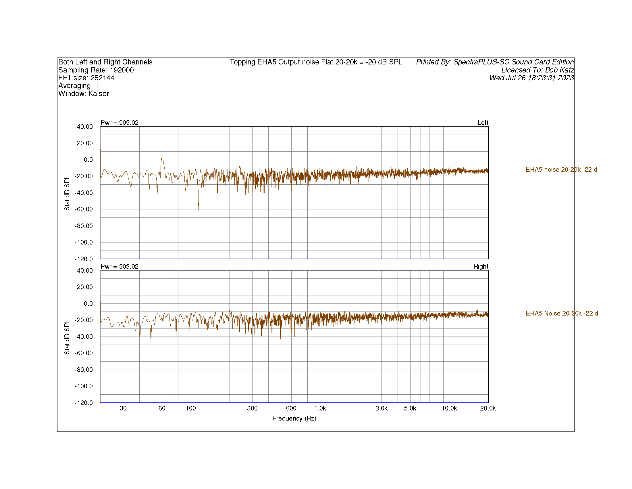
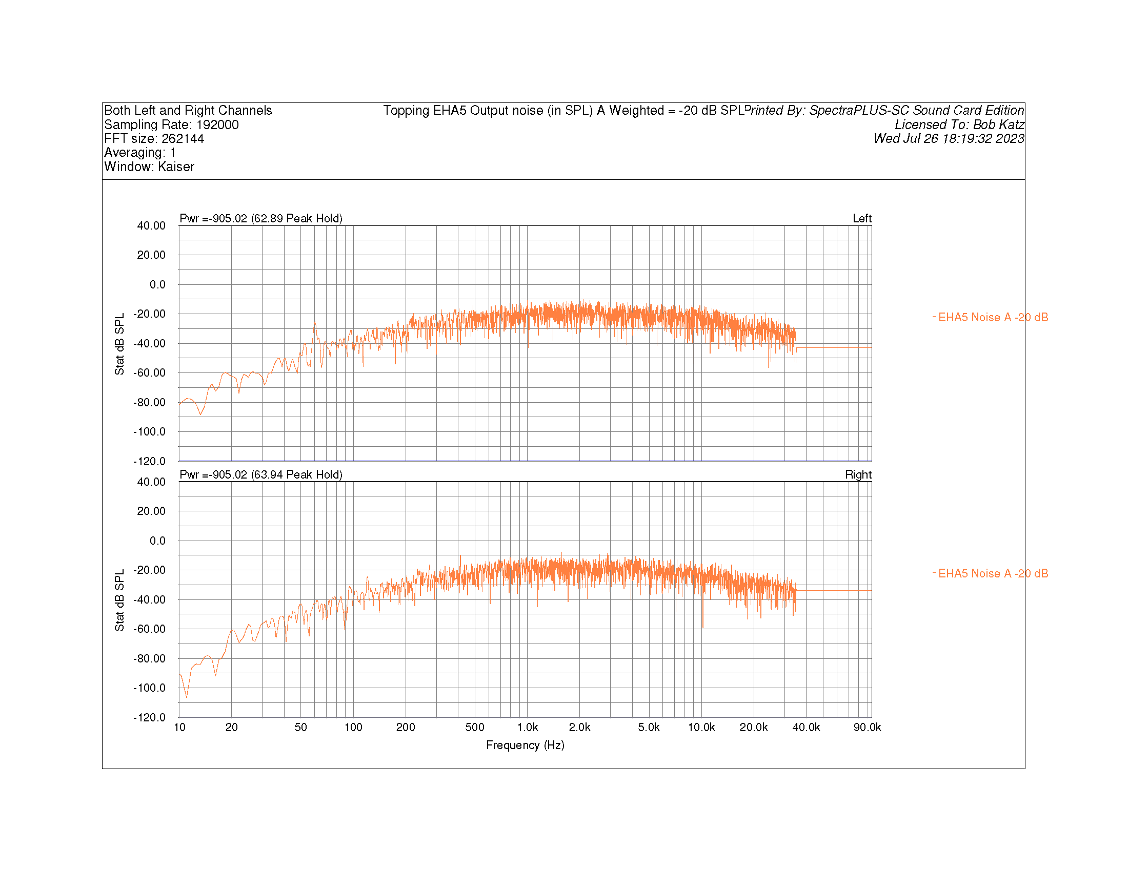
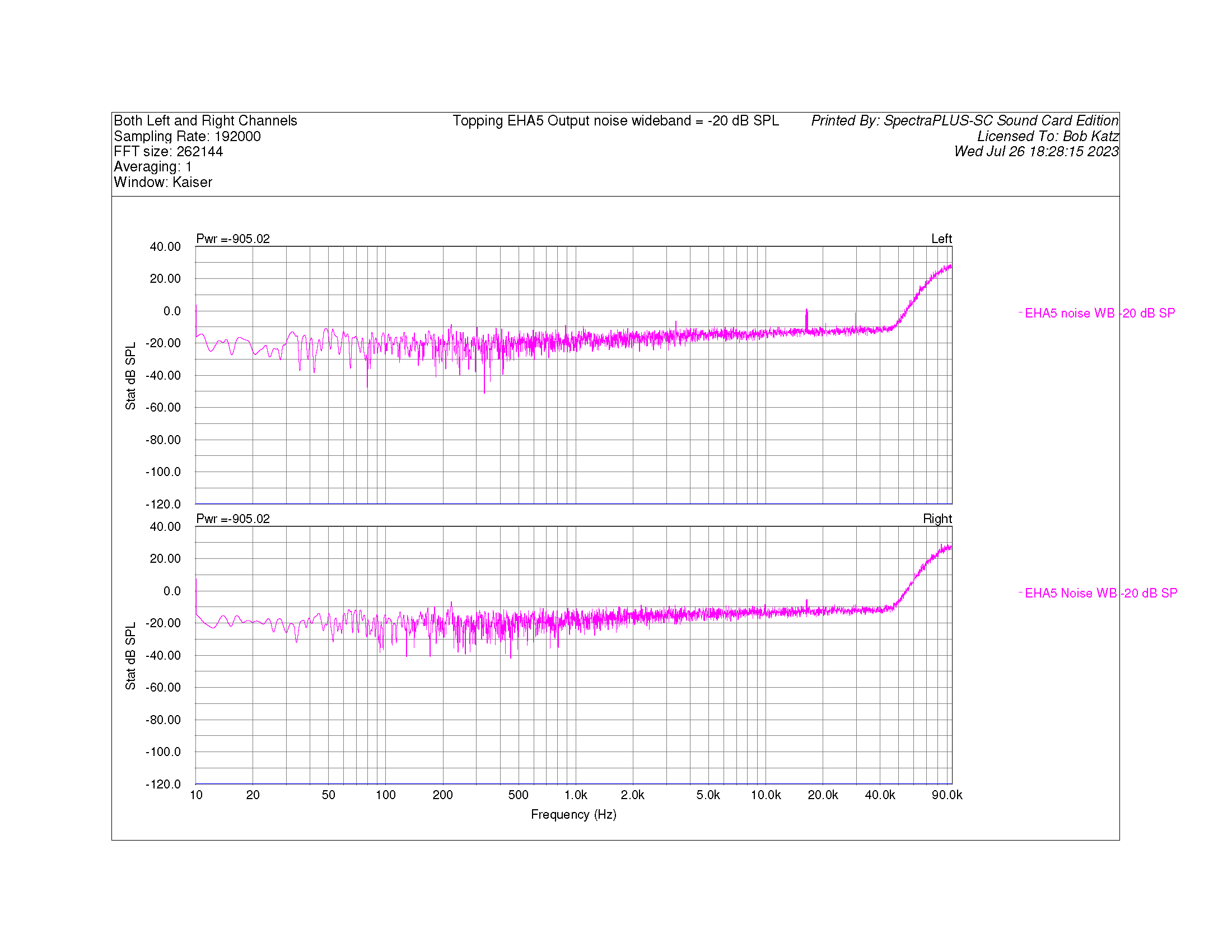
I bought the Topping and got it this week, with hopes it could be a second or extra Stat amp. I was even planning on doing a "bargain stat amp" feature at my new journalistic home "Positive Feedback", where you can find my review of the Audeze CRBNs, for example. Anway, I'm not going to publish, I don't like to publish reviews of bad gear 😞 What a disappointment this amp turned out to be. My disappointment came in stages. The first stage was an optimistic listen: "Hey, not too bad". At that time I was listening to some simple classical and folk arrangements: with solo voices and guitar, the weaknesses of the Topping circuit are not immediately obvious. But as soon as I played more complex music, full orchestra, rock band, you name it. Where it starts to get real harsh, bloated, lose dimension is with complex music, full orchestra, rock band, you name it. The more I listened, the more I started to hate this amp. I WILL BET THAT THERE ARE MEASUREMENTS THAT WILL REVEAL THIS AMP'S WEAKNESSES. You just have to know how to find out where the bodies are buried. I did find some that clearly show its weaknesses. Attached below. Frequency response (with a 100 pf load), Output level just before clipping, THD at various frequencies at normal levels and just before clipping (spectrum and %), IMD (19-20 kHz) (spectrum and %). The one thing I should have measured is a special multitone signal I use, I bet that would show where the bodies are buried, and tell us why the amp falls totally flat the more complex the music you put into it. But I'm so disenheartened and disappointed by the sound of it that I don't have the energy to bring it back to the test bench. I like to display an amplifier's measurements in equivalent SPL, based on Stax 007 and CRBN nominal sensitivity of 100 volts RMS = nominally 100 dB SPL. It helps bring a real-world perspective to amplifier measurements. Topping Factory spec for max is 700 volts RMS (I suppose the factory took this a cat's hair below clipping and only at 1 kHz). I measured maximum output at 1 dB below clipping at 630 volts RMS at 1 kHz, equivalent to 116 dB SPL. But When performing the 20 Hz THD test, the amp's DC protection circuit kicked in and the most I could get out of it at 20 Hz with a continuous sine wave was the equivalent of 105 dB SPL, 177 volts RMS before the amp shut down. So the lower the frequency, the worst the amp's headroom for transients. Plus, the THD at low frequencies is pretty bad, the transformer saturates very strongly. To see where the skeletons are buried in this amp, take a look at my measurements. The measurements to really study is a comparison of the Mjolnir KGSS HV Carbon and the Topping at nominally 90 dB equivalent SPL of IMD 19-20 kHz 1:1 ratio. I think that lurking in that measurement is at least one of the reasons why the Topping sounds so harsh and the Mjolnir sounds so pure. The primary difference tone at 1 kHz in the spectrum does not tell the story. Notice the high frequency side bands near the 19-20 kHz that begin to reveal to us the Topping's nonlinearities. There's more in the attachments. I'm sorry that I didn't do the multitone, I will some day, when I get around to it, and I'm sure it will reveal the skeleton underneath the "golden glow" of this amp. The date in the Fluke scope pictures is wrong... it's actually yesterday, 7/28/23. I have to fix the date in my Fluke Scope. Every time the battery dies, it loses the date 😞

- 112 replies
-
- 11
-

-

-
Oh, please stay away from Canare Star-Quad. Very high capacitance. The so-called advantages of the twisted starquad are offset by its disadvantages. I suggest Mogami cable designated for AES/EBU, but it's really very low capacitance balanced cable great for analog: http://www.mogamicable.com/category/bulk/dig_interface/aes_ebu/ It's very neutral, no sonic color, very wide bandwidth. The only down side of the Mogami is you have to be very fast on the soldering iron because the insulation melts very quickly. But then, good soldering technique is a badge of being a DIYer.
-
I just bought an m2tech hiface. Coming from teac by ups ground. I'll let you know how it performs. Really the best thing is to have the crystal oscillator in the dac as spdif means another PLL is involved. But I needed the flexibility to use existing dacs that i have. Asynchronous with the Centrance driver is the way to go. They have their software and hardware drivers down pat. Centrance has licensed their technology to many manufacturers and have just come out with a USB dac themselves http://www.m2tech.biz/
-
Would that be 60 pf balanced or 15 pf (two caps in series)? I just calculated a circuit using MacSpice: with a 20K source resistance, 10K load resistance and either 30 or 60 pf across the load resistor. That approximates what I have hooked directly to the input of my KGSS (without the equalization cap). With 30 pf load it's down less than .01 dB at 20K. Even if you double the input resistor to 40K you're not going to see an order of magnitude change and even that would be less than 0.1 dB. I expected that or else our typical solid state audio gear would be pretty bad news. And my KGSS measured frequency response is not affected significantly by the position of the 1 dB/step attenuator. You guys are going to have to wait till I have the inclination or a free weekend to take my input circuit apart and just measure the frequency response hooking a low impedance generator directly to the input terminals. Something's very strange here, there's no legitimate reason for the rolloff that I measured in my amp and all theory says it is not due to the input attenuator. My colleague in Belgium will also make a measurement when he gets his KGSS, made exactly like mine except using DACT attenuators. Stand by for the fireworks ).
-
I've never used the power-matched Krell systems. You're saying a 50 ohm source impedance and a termination resistor at the input to the amplifier? I had a Krell KSA-100 amp for years, class A, excellent sound, but standard high impedance input. "I'm from Missouri, you'll have to show me", so I'll continue with my own experientially-derived reactions to low impedance loads (less than 10K) on all kinds of circuits that I've tried. I didn't come about this conclusion by theory or measurement, but by listening. Once I was using a variable o-pad at the input to my power amplifier to adjust its sensitivity. The driver circuit is the excellent discrete opamp in the Cranesong Avocet, with excellent headroom (it clips at about +37 dBu balanced). This driver circuit is rated to drive most any load down to below 600 ohms. For various reasons, during a certain period of time, the attenuator turned out to be presenting a 1k ohm resistance to the Avocet. I redesigned the gain structure to produce a 10K or higher load and immediately noted a better sound quality to the system, a more open quality. So I tend to stay away from low-impedance loads on my line drivers. All levels in my system are calibrated, so the level to the loudspeaker was matched to 0.1 dB in all these comparisons. I realize there is a contradiction here in that RF circuits and loudspeaker driver circuits themselves, are able to drive very low impedance loads, but "once bitten, twice shy" so I've chosen to stay away from low impedance attenuators.
-
ONLY if you are not using a passive attenuator at the input to the amp of too high an impedance. (. If you are, I think the safest thing for you is to measure the output frequency response with your attenuator at various positions. Here are my current conclusions after my most recent round of mods: 1/2 dB of loss at 20 kHz with modified O2s (port sealed) sounds just right to my ears. I've listened to a wide variety of material that I'm extremely familiar with and it varies equally on either side of neutral when the 20K is -1/2 (no load). To my ears, the 1.8 dB of loss that I initially measured is probably excessive. Is this loss due to the approximately 10K of source resistance I'm presenting right at the input terminals? I'd have to test, or if Kevin would be kind enough to calculate. Kevin probably nailed the reasons for potential rolloff to be the input capacitance of the FET front end. In that case, it should be made clear to buyers that the KGSS is susceptible to such problems and either an attenuator of such and such impedance be used, or that it be driven by a low impedance source and a buffered volume control should be used. While some engineers I know are fond of using 2K impedance attenuators (volume controls), I've found that it seems to "choke" all the sources I've tried. Even discrete transistor circuits like to breathe, to my ears; they sound better with bridging loads, even if they are spedced to drive low impedance loads. I learned it the hard way, by actual experiment, that 600 ohm load is definitely too low, that 2K load is too low sonically, and that somewhere above that (10K is safe) is the minimum load for all the various driving circuits I've tried. This includes 5532s as well as esoteric discrete opamps with dc servos, such as Forssell and Dave Hill's excellent circuits. This leaves me with an interesting choice. I already designed this calibrated attenuator into my KGSS. Perhaps the simplest thing is for me to add a buffer stage if it is really true that the KGSS's input FET has a fairly high capacitance. Kevin? BK
-
How significant is the load capacitance to the measured frequency response of the KGSS?
-
Dear Kevin: Right. Well, there is always some form of RC filter, often due to the input wiring capacitance and any medium-to-high impedance input attenuator. I assumed my input wiring capacitance is negligible being of very short length. Do you think my measurements of (if I recall correctly) 1.8 dB down at 20 kHz can be explained by the input attenuator/potentiometer circuit I also posted? If so, then what you are saying is that automatically ANY mid-to-high-impedance input level control will introduce considerable HF rolloff in the KGSS. If so, then a slight advance HF compensation is not out of order. I just settled on four hand-matched 200 pf caps as sounding correct in my front end circuit with the O2 Mk2/Spritzer port modded! What is the input capacitance? It might be possible to design a 600 ohm (2 kohm if possible) input variable input attenuator circuit that would not be significantly affected by the FET's capacitance. This would be the best way to go about designing an attenuator so not to need an eq circuit. BK
-
Right you are. I just sealed the ports with Blu Tack today. It tightens the bottom end very nicely. Shame on Stax for having porting the Mk2 and thank you Spritzer for discovering the anomaly. I imagine they had gotten a lot of complaints from unsophisticated users about the "fart". In fact, the seal on my head is so tight that I get quite an annoying snappy fart when placing the cans on my head and/or pushing down even slightly on the sides of the phones. But I'll live with it for the more accurate bass that the sealed port produces. As a result of the tighter bass I'm considering taking down the 20k about 1/2 dB by changing the 270 pf cap to 180 pf. With some sources the high end on the O2's is a bit "high fi" but pleasantly so with 270 pf, which gives an amp boost of 1.3 dB at 20K. I think perhaps an amp boost 1/2 dB less (0.8 dB boost at 20K) would complement these phones very well. I wonder if my SR5-Golds have a port? They really don't fart much at all.
-
I should really move this question over to the port mod thread. Spritzer, are you saying that the perceived "porty quality" of the phones, which I perceive as extra energy below about 60 Hz (probably lower, more like 40) will be tamed a bit by sealing the port?
-
Well, if Kevin's prototype measures flat (into an open circuit, that's how I measured mine), we have to wait till someone else measures a current issue KGSS with its current PC board layout to know 100% for sure. Does the headphone load produce a resonant circuit? I have a friend in Belgium who just had a KGSS built by Justin and bought an O2 at my recommendations and and who has the laboratory gear to make accurate measurements (he works at Galaxy Studios) so when he gets the amp he'll measure it for us. I know that Robin is reading this thread, so since he has the "standard" (DACT?) input attenuators, I'll ask him to measure the response (balanced) at the input terminals as well since there is a difference there, should not affect response but we have to be scientific about it. BK
-
Right, I'll take a further look at it! But I'd first like to hear from others who have the latest iteration of the KGSS and can measure its response to confirm this is not an anomaly. Bob