kevin gilmore
-
Posts
7,201 -
Joined
-
Last visited
-
Days Won
21
Content Type
Profiles
Forums
Events
Everything posted by kevin gilmore
-
its all stax tube amp with mills style non-inductive plate resistors. thats basically all of them except for the t2.
-
suggest you solder all connections associated with the filaments. and then solder them again.
-
someone needs to post very high resolution images of front and back, then will correct schematic if necessary
-
suggest you redraw that part of the schematic that you think is wrong. there have been mistakes in stax schematics in the past. especially the t2. once it enters production and works...
-

-
so single stator headphones. like beveridge speakers, but done horribly wrong. 2000v bias. single supply ac coupled 450v with dual in parallel bsp135 as current sources, with dual bsp125 in parallel driven by opa1642 dual opamp. without it being on your head, no seal for the diaphram. lots of dsp to equalize this mess. all analog input signals digitized and then stuffed into the dsp. another example of stupidass (tm&c) engineering. these people should get together with the engineers that did the eha5. so much engineering money wasted. edit: no dsp found.
-
does look like the same amp. however the quality of the western electric tubes with all that fluorescence on the glass is definitely worrying me, clearly they are not pumping down the tubes enough. or not enough getter.
-
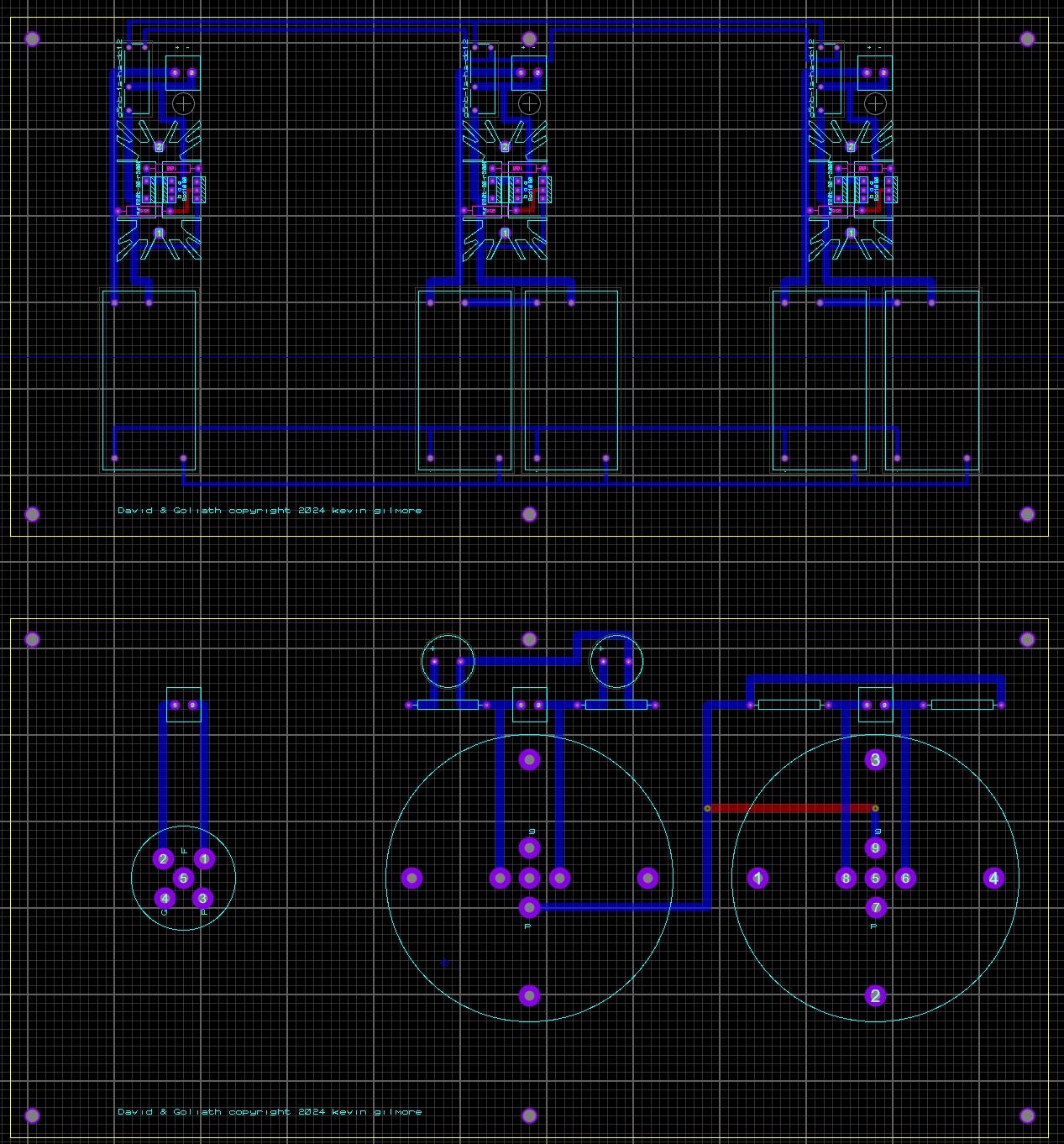
there will be 4 output boards. 12 x 6 inch each. filament boards will stack on them, each filament board will have 5 x 5v 4a switchers. 2 switchers in series for the 211 so chassis is likely to be a bit over 24 inches wide and 20 inches deep. updated picture
-
i like that. i also like "david and goliath"
-
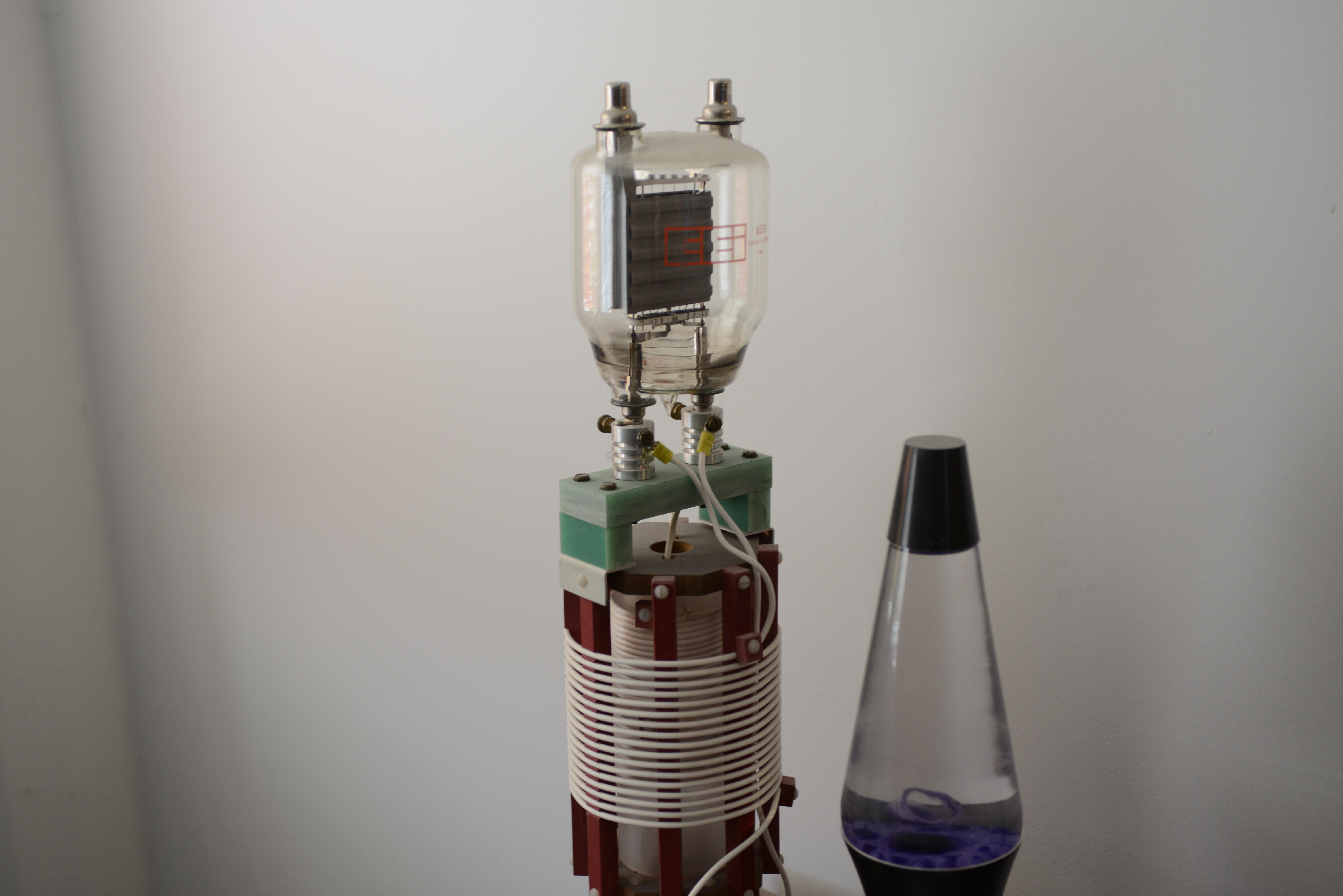
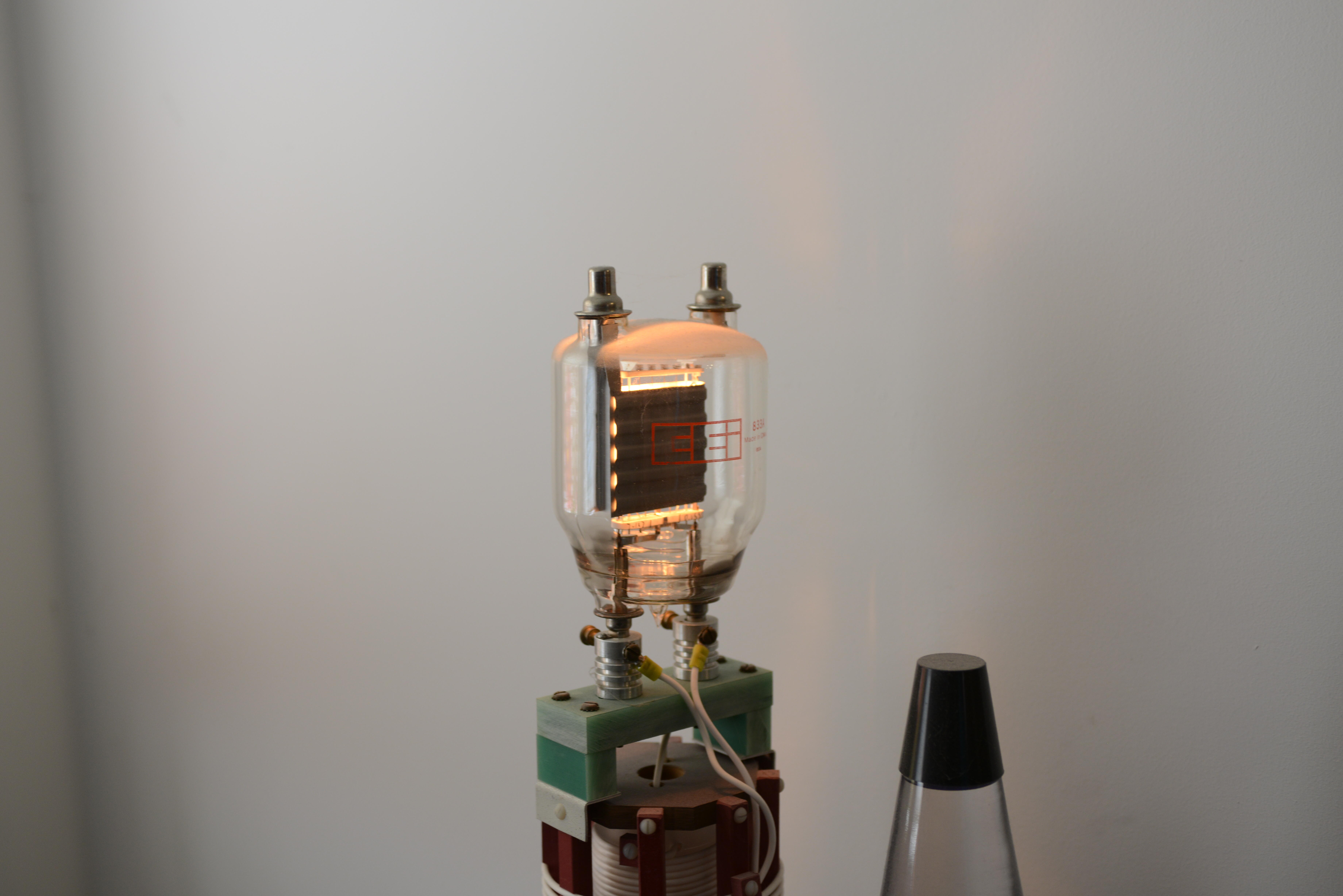
So this started a few weeks ago when someone found a picture of my 100 watt night light. Its an 833A tube. (new picture below) And he wanted a megatron made from 8 of these. (10 vac at 10 amps each tube) so 800 watts filament power just for the output tubes. By the time you make the +/- 1kv power supplies running at 40ma, and the power for the 300b driver tubes etc, way past the limit for usa 120v 20 amp service which is 1850 watts. And with the top of the tube at silly and dangerous high voltage... bad idea. So i started looking for slightly less silly alternatives. I think the 211 tube fits the bill. running with +/-750v power supplies at 35ma. So a megatron with 211 output tubes, 300b drivers and a high gain input tube. unless someone has a better idea.
-
depends on what kind of power supply is inside. if its a switcher, it might benefit the input caps for a 30 second slow ramp. if its a linear supply, probably does not matter.
-

Hey Head-Case, what's your bandwidth like?
kevin gilmore replied to Knuckledragger's topic in Off Topic
my orbi is getting glitchy too. replacement is $1500. likes to drop the dns once a week. i'm getting 1194 download and 24 upload. if i get the newest orbi, i can get up to about 1600 download with top xfinity tier. i don't need that yet, and then i would have to upgrade every switch in the house to 2gb or faster, and those are expensive too. also looks like i'm going to get a atsc 3.0 tuner very soon. there is a chicago station now that is broadcasting 4k cartoons. 3 stooges in 4k is da bomb. -
goldenreference low voltage power supply
kevin gilmore replied to kevin gilmore's topic in Do It Yourself
i don't remember. definitely can add 1 wire and not use it in shunt mode. -
goldenreference low voltage power supply
kevin gilmore replied to kevin gilmore's topic in Do It Yourself
you are going to need to change the lt1021 to the 5v version and recalculate the resistor ratio. 3v across the current source is not enough for it to work properly. even 5 volts is cutting it close. the minimum tested voltage for this design is 12v output. -
clever idea but you then need a jumper block.
-
Newly developed ground loop hum in a Stax SR-007A's right channel
kevin gilmore replied to plaurids's topic in Headphones
switch the tubes. if the hum does not move, its the headphones. -
Newly developed ground loop hum in a Stax SR-007A's right channel
kevin gilmore replied to plaurids's topic in Headphones
unless one of the tubes is slammed to one of the rails, rebiasing is not going to help. but you should measure the dc output voltages. -
unbalanced/balanced to balanced tube input
kevin gilmore replied to kevin gilmore's topic in Do It Yourself
cp1117n is normally closed, so no output voltage. you need to power it to turn the hv on. -
goldenreference high voltage power supply (GRHV)
kevin gilmore replied to Pars's topic in Do It Yourself
kgsshvpssicfetsinglenewleftsws - CADCAM.ZIP -
goldenreference high voltage power supply (GRHV)
kevin gilmore replied to Pars's topic in Do It Yourself
kgsshvpssicfetsinglenewleftfatsws - cadcam.zip 12/25/2015 definitely on the google drive. -
i posted this elsewhere. here is a copy Its all about size (as in core cross sectional area) and maximum flux before saturation. its obvious from the graphs above (posted elsewhere) that the core saturation of the eha5 transformer is about 1.4 tesla indicating the cheapest of core materials. better and much bigger transformers are available from lundahl and edcor. which will both give 20hz to 20khz +0 -1 db and will actually do 1800vpp with a 50 watt amplifier over the full frequency band. without series resistors. without filters. as far as i can tell lundahl does not specify maximum field strength. edcor does and its 2.01 tesla. there are custom c cores with magic materials that can do up to 2.5 tesla. these are a bit expensive. the ll1630 mentioned above (posted elsewhere) will NOT do this. core size is too small. you need a transformer with a minimum of a 30 watt core. The 60 watt edcor are MUCH better. the ifi iesl which is extremely sensitive to power amplifiers is yet another example of a poor design with a tiny transformer. does not matter how carefully you wind the core if you drive the transformer into saturation. the result will be a box about 3 times the size of the eha5. and a weight of about 20 lbs. cost about $600. nope, no cheap way of doing this.
-
here is a link to simmcon's takedown of the eha5. its mandatory reading for everyone. https://www.audiosciencereview.com/forum/index.php?threads/topping-eha5.42149/post-1712440 in other news, birgir sent me a srd7 to test. in other other news, i have finally found a company that will sell me cores and bobbins in small quantities. so making electrostatic transformers becomes a possibility.
- 112 replies
-
- 11
-

-
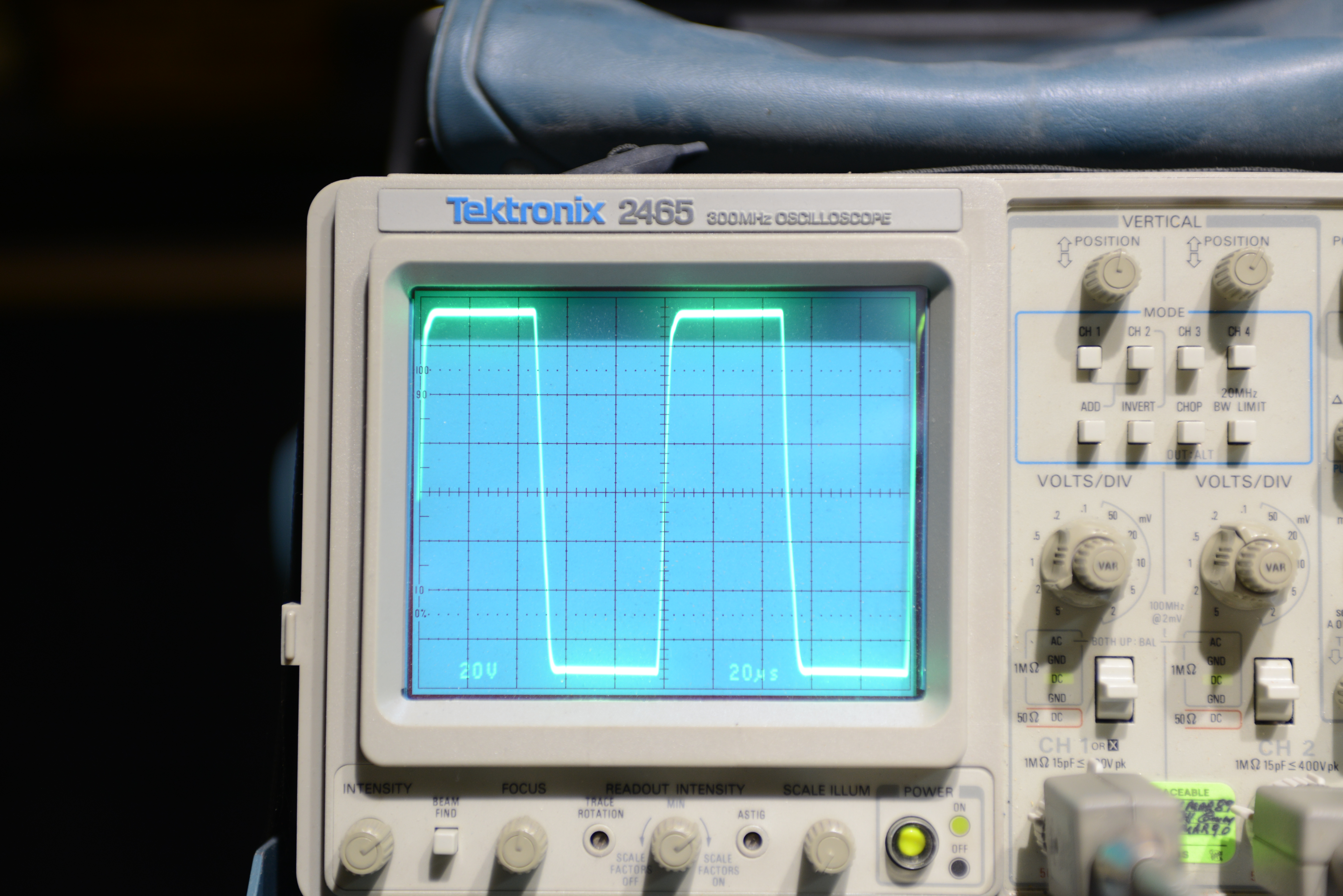
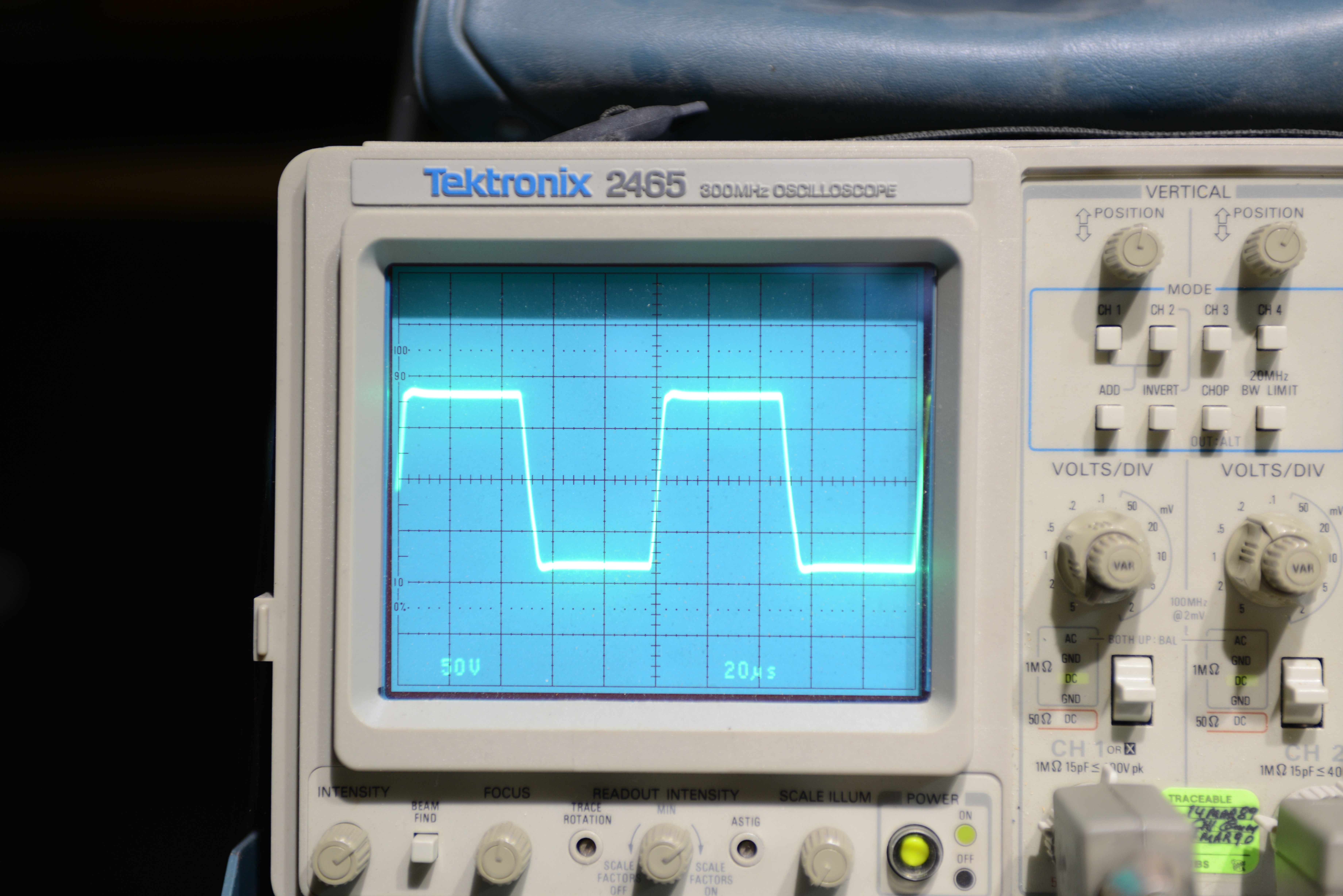
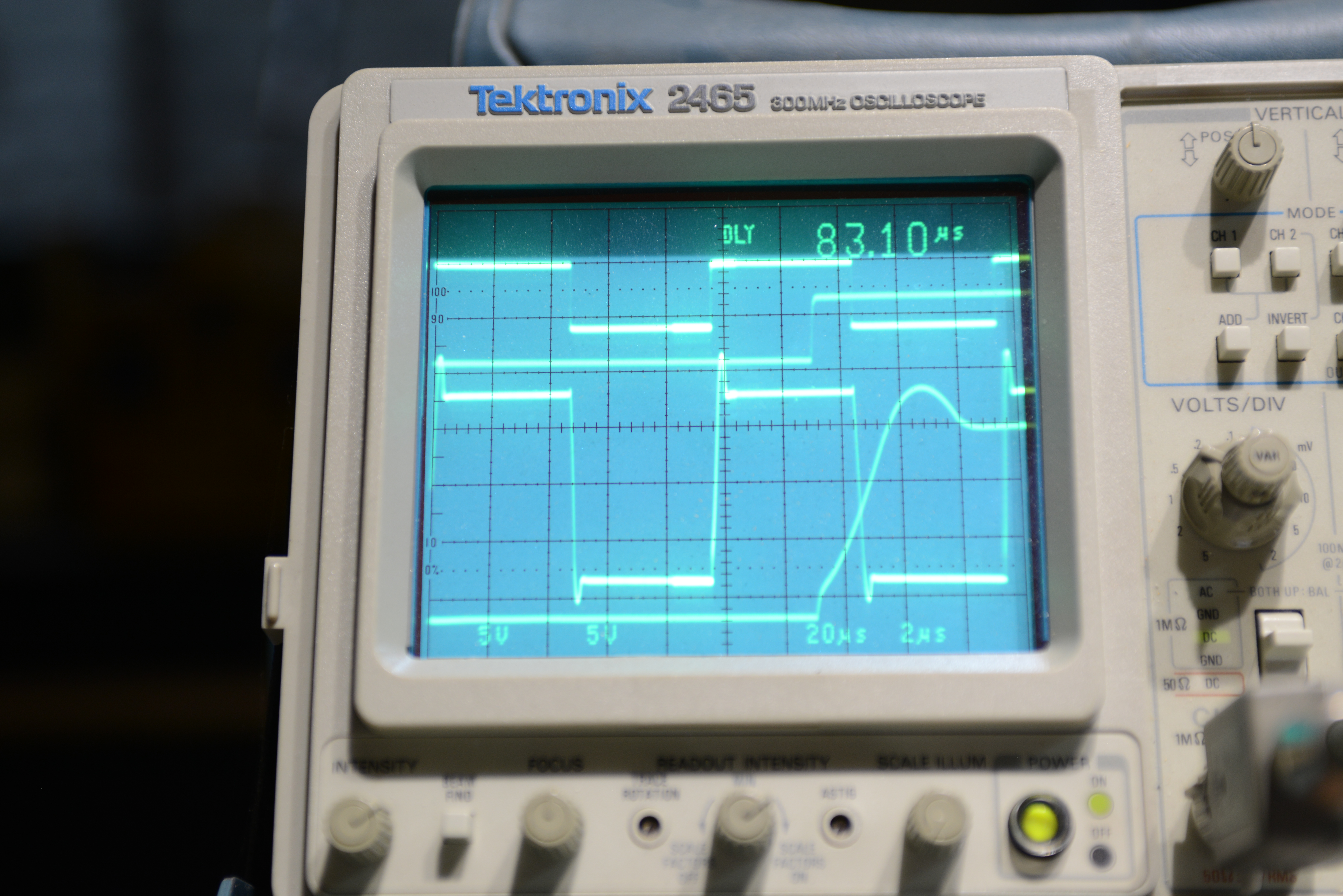
so here are some more pictures, obviously faked. This is the kgsshv-carbon built by birgir and given to tyll as one of his 2 reference amps. Into a standard 120pf load. right at the limit of my scope probe, have to find the higher voltage probes. first picture 20 volts per division, next 2 are 50 volts per division. all are 10khz square wave. reference cap beginning to bubble due to heat.
-
well if i used one of my digital scopes, then did an edit on the computer and then played it back on the scope, its probably fairly easy. but on a real analog scope, it would be some kind of impossible.
-
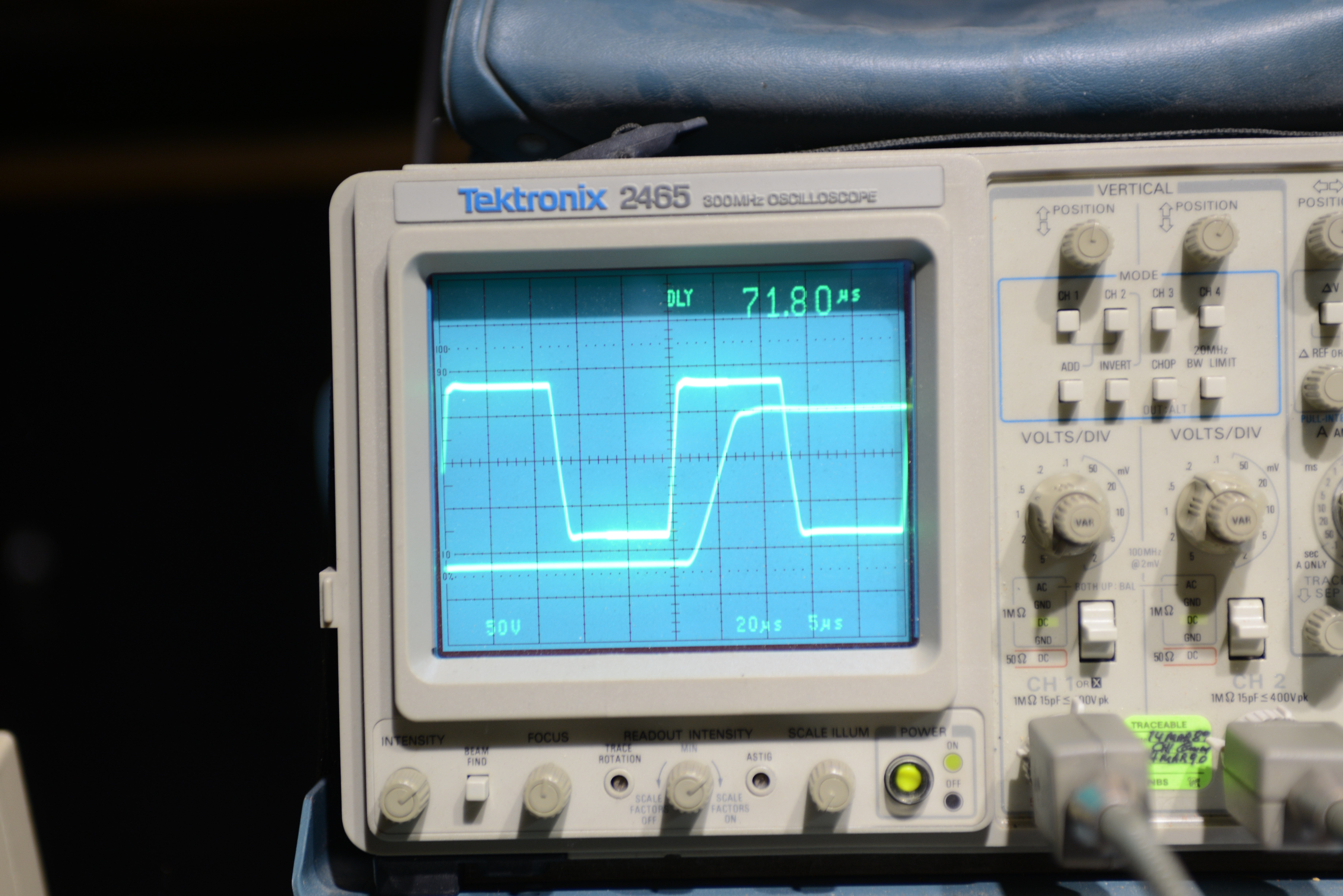
So a person accused me of faking my scope picture, because it had to be my signal generator. And that the amp performed better at the higher gain setting. I completely disagree. Q15 has no emitter resistor and the resulting gain of just this transistor is 30db. which makes the miller capacitance absolutely huge. which is why you see two different slew rates. the first bit is due to the output amp (everything left of r12 which is a diamond buffer driving a pair of current mirrors driving another diamond buffer). The second bit is due to Q15. edit: shenzen audio is now selling these things brand new in the box on ebay for $50 off. soon it will be $100 off.