Jump to content

kevin gilmore

High Rollers
  • Posts

    7,094
  • Joined

  • Last visited

  • Days Won

    18

Everything posted by kevin gilmore

  1. left 3 top and bottom blue resistors are the segment bits 5.11k 02C resistors and all the other blue ones in that row are 10.2k 69B resistors and the other blue ones in that row are 5.11k 130 is 13 ohms top switches v- = ground bottom switches vcc=ground
  2. No schematic for the power supply that Kerry did. Unless he has it.
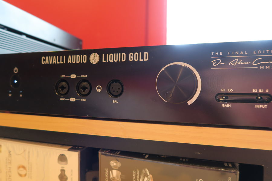
  3. the cavalli liquid helium definitely sounds a lot like daffy duck.
  4. note: liquid hydrogen is stupidly dangerous. besides which you are unlikely to get anyone to sell it to you. liquid nitrogen is better, and very cheap. been there, done that many times, no difference can be detected. cryo'd cables,cd's,tubes, flowers,bananas... liquid helium is even colder, and very expensive
  5. that picture is not the holo dac. its something else. the holo dac has only a few caps.
  6. actually the MIT cables are more than a resistor to ground. There is all that hot-glue. Dripping piles of hot-glue. And a couple of very small value caps. the guy at double-helix cables clearly has absolutely no understanding of electrostatic anything. Unlikely to have ever opened a quad56 or quad63 because if he had he would know that there is a reason why the wires are so thick. and so goes with his fancy silver wire in a high capacitance dielectric. Go to his website and count how many turns on the braiding and figure that the capacitance of his cable would be at least 3 times that of a stax cable. and then the BS about not plating the silver with gold because gold "slows down the signal" and yet all his connectors are cheap gold plated crap. etc. No one should help idiots like this mess up other peoples stuff.
  7. not high enough resolution to see what is going on. like whether its sign magnitude etc. and the power supply box obviously does not have enough capacitors. This is overly goofy. Especially if one cap shorts out, repair could be just about impossible.
  8. that one might be really good, real and matched cmos switches instead of digital outputs. But its pcm only, the cmos switches are not fast enough for dsd
  9. well this guy clearly has no clue, and does not understand capacitance. or the voltage ratings on the wire. and i'm not going to sell him any 5 pin stax plugs reminds me of the idiot that made a krell ksa5 power cable filled with magic pixie dust and managed to get the wiring wrong and did a number on that amp.
  10. yep, upsampling. plus if you are going to keep the original samples you need higher resolution to extrapolate the pieces in between. so at least 20 bits. one of the main reasons is filtering. for 16/44, you really need a multi pole output filter to prevent aliasing, and all the analog filters that have been used in the past have significant phase shift among other issues. so you bump it up to some very high frequency, then a simple single pole filter way outside the audio band, say 100khz. then no phase shift at all in the audio band. and you make perfect discrete high power pure class A switches.
  11. its one of the things i'm thinking about
  12. its a cfa and the gain is high enough that trimming is probably not necessary. But i will look into it
  13. found this gem on lampizator website •DHT triodes in single ended anode follower configuration as Lampizator signal tubes (45 or 2A3 or 101D) really? i did not know that tubes worked that way. And something he does not say for the SE units, they invert phase. for the calculated power and voltage levels depending on the tube, 5% thd second harmonic. 275V top of plate resistors, 130V on the plate, 55 volts on the cathode. Not a lot of room to work with with this gain.
  14. no way to set the midpoint, on congo5's unit, it is about 5v (well there is, but its a pain, have to trim resistors)
  15. the flavor of the month is clearly r2r discrete dacs MSB,dCS,Soekris,Lampizator, T+A, Totaldac, DSC1 (an interesting variant),new audio-gd, Holo Spring and probably a bunch of others coming. the 20 bit multibit that schiit uses is the highest resolution monolithic integrated circuit part available. (no dsd) everything else is delta/sigma stuff
  16. well its 2016, soon to be 2017, and it might as well be 2009/2010 because lampizator is round 2 of singlepower. I was waiting to get a picture of the board so that I could disprove just about everything lampizator has said, and found it. here it is The balanced output board is more of the same, its clear that the output tubes are a common cathode design, simple diode rectifiers and cap for the filament power, resistor plate load etc. This is an OUTPUT stage! Not a I/V converter. Not anything else either. Output capacitors are connected to the board and mounted with left handed skyhooks (also known as air) to the output connectors. Some recent lampizator complete lies all but one completely disproven by pictures birgir has 1) the soekris dac is modified to be a current output dac, and the tube stage is the I/V converter OK, flat out lie, the pictures shows that the voltage output of the soekris module is wired directly to the input/attenuator board. In fact there is absolutely no way to modify a R2R ladder dac to be current output, you need a multiplying dac, or a stack of current switches. 2) the soekris dac is modified by removing the +/-4V power supplies and driven with a super fancy (as in pair of 3 terminal regulators) power supply, truth is that board up front is just a +/-12V simple power supply that also supplies power to the attenuator board. 3) the one I can't verify, that lampizator programs completely custom and proprietary firmware into the soekris. No maybe a few filter changes, but the bulk of the firmware, not a chance. But really, the chance that this idiot can program something like that, you gotta be kidding. TRUTH! The soekris dac is used as both pcm and dsd, its hard to call something chipless with lvc595 shift registers as the output switches. The output of the soekris dac goes directly to the attenuator board, the attenuator board goes directly to the tube output stage. unregulated High voltage power supply also reminds me of Mikhail. etc. and people are paying up to $20k for this, pretty soon some will be comparing the various kinds of wood used on the base of this thing.
  17. Here is what I have to say for all dac's these days. Even though this has been going on for 25 years or more, there is still so much to be done for both the hardware and firmware/software. I'm sure that people 20 years ago that sunk >$25k in to the krell sbx64 stack are kicking themselves for doing so, as today's price on that pile is just about a giveaway. For R2R discrete dacs, you have your choice of 2's complement dacs (basically 1 ladder per channel per side) with associated issues with switching around virtual 0v and sign magnitude dacs which are twice as many parts, and can generate interesting new distortions when the 2 sides are not perfectly matched. then there is the firmware and associated iir, fir, closed form etc filters, everyone tries to make theirs proprietary, until someone open sources this, it will continue. So spending $5k or more on something that may have been close to $20k seems like money dumped into the trash can. Especially stay away from lampizator, in my opinion, the new singlepower. Buy a holo spring and sit on it for 2 years when all sorts of new everything should show up. or if you are pcm only and going to stay that way, buy a yggy. part 2 more and more people are doing upconversion from pcm to dsd128 and dsd256 and like me seem to like the sound a bunch better. Its so much easier to design one switch per channel (and match the rise and fall times and exactly control the off and on voltages) than it is to design 24 or 28 (2's comp) or 48 or 56 switches (sign magnitude) per channel, then double that for balanced.
  18. http://bbs.audio-gd.com/dispbbs.asp?boardid=2&Id=30313 audio-gd version, 8 for balanced sign/magnitude
  19. pars needs an 8.5 digit dvm!
  20. the 4 tube DHT version pictured last is definitely NOT srpp.
  21. the lampizator site clearly states that the tube stage does the I/v conversion. but the pictures clearly show the voltage output of the soekris dac (there is no current output) going directly to the attenuator modules, there are 2 because its balanced. there seems to be no discussion of the actual tube output stage, and rarely have I seen cathode followers done as dht, so its probably a low gain plate output stage likely with a plate resistor. Also the pictures would otherwise show 4 separate filament windings (well 5 counting the diode rectifier) if it was cathode follower. even Mikhail would have a hard time building a piece of crap like this.
  22. And the bottom of the thing is wood. Would love pictures under the board with capacitors in parallel or series attached to nothing. Even mikhail never did anything in wood (that I know of) although there was a partial wood front panel. for more amusement there is a company out there modifying teac products replacing regulators with some other regulators and some capacitors with some other capacitors and charging more for the upgrade than the thing cost in the first place.
  23. won't make any difference
  24. a lot of times it is so much easier than that. many of the chips in dac's have unique footprints and are easy to identify without having to resort to more unique measures. The firmware in them however is much much tougher to extract, which makes sanding off the chip numbers even more stupid. Unless they are using super cheap junk opamps etc. or 5534 chips for the i/v conversion.
  25. I think it should work as is. may have to adjust the value of a trimmer pot to get to zero volts output
×
×
  • Create New...

Important Information

By using this site, you agree to our Terms of Use.