kevin gilmore
-
Posts
7,201 -
Joined
-
Last visited
-
Days Won
21
Content Type
Profiles
Forums
Events
Everything posted by kevin gilmore
-
schematics t2schem.PDF t2schempower.PDF
-
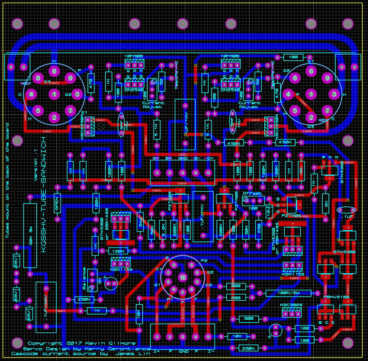
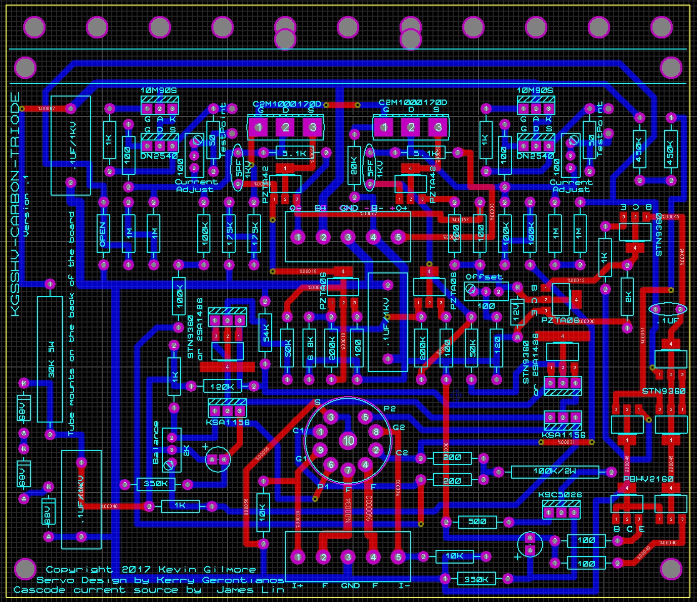
todd added zip files to the attach list, so please look at these and see if I made any mistakes kgsshvcarbontriode.zip kgsshvtubesandwich.zip
-
length or width, you are asking for width. for that box, inside is 6.3 x 11.8 so two amp boards would fit on one heatsink already. no room for anything else, would have to be a two box. I centered everything on the board, so when you put them next to each other, the tubes align.
-
updated the board pictures, either stn9360 or 2sa1486 (people should have bunches of them, still available) that transistor is roughly .6 watt 5 watt resistor is designed to give about 200v 3 x 68v zener in series would be around 210, so if the tube is not warm...
-
they are not the same kind of plugin's that fit in the 7000 series scopes. but they are plugins that require a power chassis.
-
Kerry needs to publish the latest schematic with his servo. posted version does not have enough current to drive the opto. would still work without the servo
-
actually the cathode sits at +1.5 volts, very similar to T2.
-
not to scale, carbon board is 5.45 x 4.72, tube output board is 5.6 x 5.52 newest versions of the boards

-
one capacitor in the audio path.
-
well that is one way to make a fully dc coupled megatron
-
looks like the best I can do is about 5.7 inches current gg board is 4.7 inches
-
that's enough for today
-
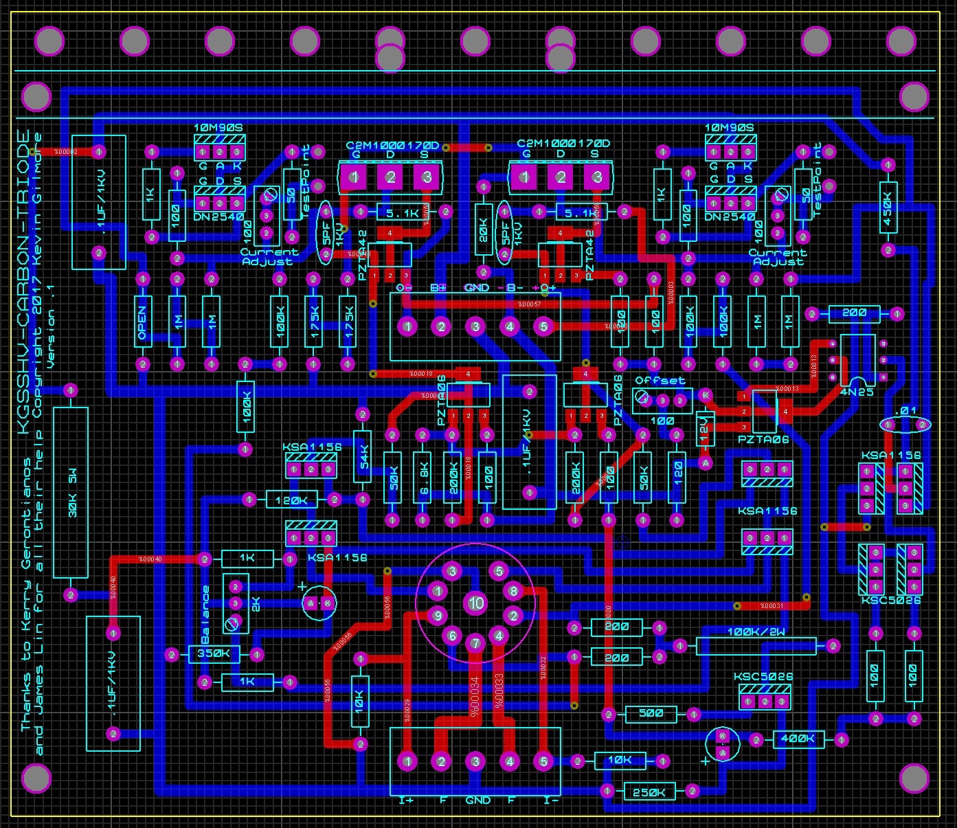
using Kerry's servo, but a resistor to make +200 by the way the alternate name of this board will be t8000DR (DR as in done right) edit: fixed font sizes
- 261 replies
-
- 10
-

-
18 to 20ma guitar amps will bias them much more, but they run at only 400v total
-
i'm not sure what the mjw18020 is designed for, but for dc use, its going to blow up over 450v
-
A simply regulated +200v rail will reduce the power, same with the input current source. Then up to 450v rails what I published I know works, now time to perfect it.
-
You need a bigger house, hell I need a much bigger house
-
I could publish what I think the t8000 is, but take my design, and replace the output stage with stages 3 and 4 of the srm727 and it's going to be real close. Probably a stacked current source in stage 3 with current production transistors. and yes, you can replace the output fet with a tube in addition more fun ahead
-
Well its not like the stax mafia aren't busy and we certainly are not going to do an output stage with 8ma of current, and therefore no reason for a 4 stage amp, and since tube inputs seem to be the big thing lately, well might as well take the kgsshv-carbon design and replace the input fet with an input triode. bonus, no low voltage supplies. not a bonus, ksa1156 and ksc5026 run at close to 1 watt each. I should have a real t8000 end of june, but this should keep some of you busy. I expect joamat to have one built in less than 24 hours. no, no circuit board yet about 70 volts on the plate of the tube, same as t2. optical servo from kgsshv-carbon will work fine (but then you need the low voltage supplies) kgsshvcarbontubeinput.PDF
- 261 replies
-
- 11
-
-
computer audiophile, there were links somewhere in there to a person in Russia that did extensive testing with the appropriate equipment. also did the holo, denafrips etc I have listened to 2 of the cheaper schiit dacs. for the price, you would expect them to be hard to touch except for the fact that there are plenty of things on ebay that do a better job for cheaper.
-
Ripped 2300+ sacd's over a 3 month period last year 2 at a time. me unusual? No never
-
I have extensive listening experience with many of the schiit products with the exception of the yggy. They all have pretty miserable performance. Others on computeraudio have tested the yggy in comparison to other products, and you can probably go and read for yourself. the soon to be released complete soekris product is going to be significantly better in every possible way, and in addition it does dsd. and its about half the price of the yggy. Since 25% of my music library is dsd, the yggy was never an option regardless of price. I expected never to see another product with burn marks on the circuit board ala singlepower. Then the liquid carbon and the jotunheim showed up. left the jotunheim on for a solid week and well the thing overheats. I'm convinced that I could do a better amplifier for the same price, designed in America and assembled perfectly in china. In fact audio-gd has already done so a bunch of times. The particularly horrible unbalanced to balanced conversion of this amp combined with the BS associated with pivotpoint shows that Jason is an excellent salesman, and is just recycling designs from 40 years ago. sounded like shit then, sound like schiit now
-
the pcm1702 definitely require + and - 5V, so that is the analog supplies the +5v digital on the board has a regulator and the relay is 12v, so the digital supply would be 12V
-

stax mafia circuit boards see updated links on page 5
kevin gilmore replied to kevin gilmore's topic in Do It Yourself
the whole archive is 20GB and is a real mess, lots of cleanup needed, so many different version etc. here is the one you asked for. goldenreference.PDF if anyone needs other pdf's and know the name, I can add here -
the feedback mod is only for 727