kevin gilmore
-
Posts
7,129 -
Joined
-
Last visited
-
Days Won
21
Content Type
Profiles
Forums
Events
Everything posted by kevin gilmore
-
the torr seal is holding for now, hopefully the parts coming in are usable. But if you can find someone with the original parts new or used or even broken I will be able to remanufacture with the threaded rod. Very surprised at the idiot that designed this, way too much stress on a 5mm threaded rod with 75th side walls may even switch to brake handle actuators and then recreate the stops for the cables kind of like this idea http://www.ebay.com/itm/MOOSE-RACING-One-Sided-Made-to-Order-37-57mm-Clamp-On-Downtube-Shifters-Adapter/152651747057?_trkparms=aid%3D222007%26algo%3DSIM.MBE%26ao%3D2%26asc%3D41376%26meid%3Dd588e1824d874fb78025ab745f3baefc%26pid%3D100005%26rk%3D3%26rkt%3D3%26sd%3D152651737182&_trksid=p2047675.c100005.m1851
-
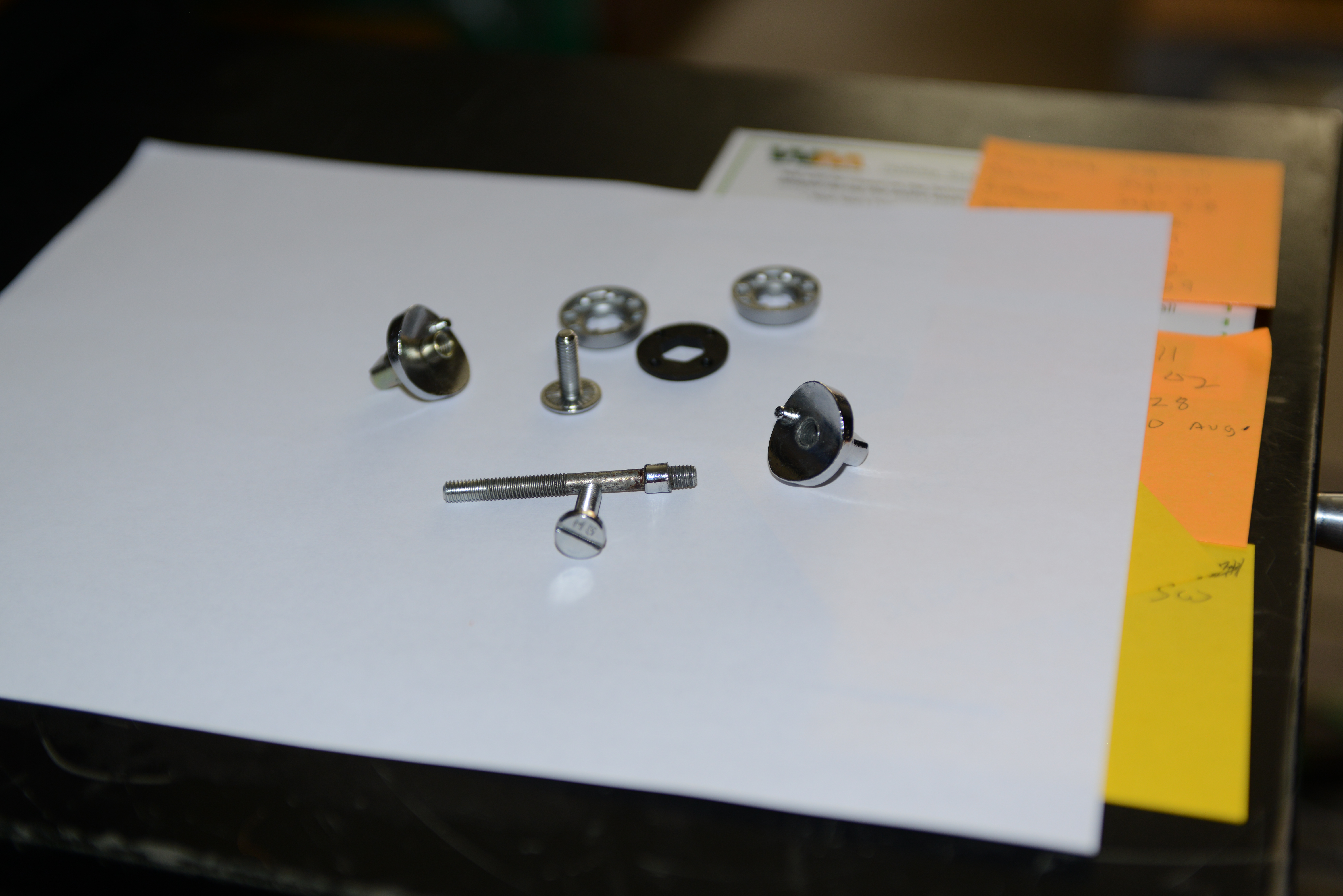
shifter boss assembly is broken, the threaded rod has the remains of the attachment for the right side. sent an email to kozy, nothing back yet. also ordered thread repair kit with m5 inserts, and 1 meter long 5mm threaded rod. first kind of epoxy pulled out in a minute, trying torr-seal now. the way it worked was that the rod was attached to the one end with thread lock and then the other end, you can tighten down and then the black piece holds it all in place. then the shifters are attached with bolts on each side.
-
well they are more annoyed by birgir's comments. i'm slightly more politically correct. (when I wanna be)
-
that is what I bought, should be here tomorrow, really don't like that you have to epoxy everything together. The cannondale part number is A095 Kit, Shift Boss, 1.75 inch diameter tube, listed as obsolete please pm the seller and see if he will sell just the whole shifter set
-
next time he visits it has to be in the summer, need to put the top down, there are still marks found a generic repair kit that may or may not actually fit the down tube. instructions say to epoxy all parts of it together to the tube, who knows, its a cheap thing
-
nope, 5 feet 2 inches (on a good day)
-
yes please. stupid ass cheap parts 1.75 inch diameter down tube
-
anyone know of a place that sells vintage shimano parts, the shifter just cracked off the 24 year old cannondale tube shimano 105sc sl 1056 with bolt thru the tube (or recommendations for a new bike in the $2k to $3k range because anything i'm likely to do is going to be a hack job)

-
who made the thing, and inside pictures please. likely the thermal fuse inside the transformer went open, may be able to short it out.
-
my opinion is that it is very close to a 717. definitely sounds different from a 727.
-
goldenreference.PDF
-
new division. *schiit
-
maybe there are 2 other caps hiding in there. pretty much have to be. max gain for a 6sn7 is 20 and max gain for a 6sl7 is 70, so 1400 would be max voltage gain at 6% distortion. cut it down to a gain of 500 and you are still at 2% distortion. with no feedback frequency response is going to be much worse at 20khz, like 6db. the resistor current sources make it worse. stupidly poor design that seems typical of schiit. kind of wonder that if they ever did make something really nice, people would notice.
-
there is only one coupling cap per channel, so the circuit may be slightly different than shown. plate resistors instead of cascade current source is pretty lame these days. Completely open loop with no feedback is the result of not enough overall gain, and this is going to make the thing highly unstable. at least they used Justin's stax jack. The only piece of quality in that mess
-
my favorite power supply is the GRLV, it outperforms everything I have seen by a large margin.
-
you probably want the version with the on board servo then. my guess is that the input impedance is something like 10k now that the lsj and lsk dual parts are available, a 2 channel version would be possible with a much higher input impedance
-
so all of that (the last pic) is that just the headphone amp, or is it also used as the output buffer for the xlr/rca way goofy if its just for the headphone. and I really don't like digital volume control.
-
I have not listened to the 1541, waiting for a USA distributor. the lower end unit is probably similar to the denafrips unit and the same price. Both are likely very good, Birgir has the denafrips and the original soekris boards
-
output buffer may be a diamond follower, hard to tell. rest of it after the dac certainly looks like stacked current mirrors. certainly a complicated design similar to what you see inside integrated circuits. obviously assembled with high resolution pick and place machines. much better built than a lot of stuff I have been seeing these days. Now a year or 2 to make the software perfect and the thing will be gold. no sanded off parts either like the denafrips, so they are proud of their work. Only one board error with that hand soldered diode. nice stuff and an indication of whats coming.
-
Lucky that birgir does not have a basement, otherwise the collection would be much bigger and heavier. I happen to know someone with this problem. however he does cheat, no way he can put his car in the garage. last I knew there were several hundred pounds of transformers where the car should be.
-
one comment about the tubes, have tried many tubes on testbench, 12au7,12ax7,12at7,7308 etc you need a mu of at least 33 and a transconductance of at least 12500
-
the card edge sockets were .156 spacing on everything I have seen. The connector for the aux input slot is the same thing.
-
More difference in the tube between 100 and 150v
-
The VAS and output stage are from the 717. Resistor pullup on the vas stage. The 727 had a current source that replaced the resistors and really was better once you fix the local feedback. I'm sure that the stax mafia can make retrofit current source boards birgir's thoughts on the sound are exactly the same as mine, the high end is rough and screechy also all the extra connections on each of the plugin boards including the servo are going to get noisy over the years. very cheap connectors, not the augat that I use. also kind of wonder if they really are rated for voltage
-
per channel the -15v current is around 8ma tubes, 6922 and 7308 come to mind. there are also some subminiatures the change in sound with higher voltage is VERY subtle...