kevin gilmore
-
Posts
7,201 -
Joined
-
Last visited
-
Days Won
21
Content Type
Profiles
Forums
Events
Everything posted by kevin gilmore
-
was planning on using the teflon versions on ebay. but i think that ceramic one is exactly the same size.
-
no real reason to shrink the filament board, but go ahead and try. the output tube spacing is already at the minimum and that results in a specific board size. no reason for the filament board to be any smaller than that because all the holes need to line up. filament board stacks on the output board.
-

the problem of Reference Amplifier for Electrostatic"
kevin gilmore replied to Omega_ELS's topic in Headphone Amplification
the power supply is clearly labeled as +350 and -350. so an absolute maximum of 1400 volts peak to peak stator to stator. which is 500vrms. not 630 vrms. the same as every stax amp with these power supplies. srmt1 all versions, srm717 srm727 etc. looks almost identical to the koss circuit with bipolar outputs replacing the mosfets. push pull. no idea of maximum output current. lots of opamps with huge amounts of feedback. if its cheap enough, might be worth it. probably not. -
owning a z06 with a zr1 on order, i am more than happy with these results. z06 beating cars that are 3 times the price or more, seems pretty impressive. and driven by gm engineers. pretty sure a real race car driver would do quite a bit better.
- 2,115 replies
-
- 4
-

-
- Golf Mafia
- M Sport
- (and 1 more)
-
chuck mangione dead at 84.
-
2sa1968 is in fact a PNP 900v. 2sc1968 is a 500mhz rf amplifier.
-
wow, you take off 2 hours to watch a movie and then all of this. if that class B output section could actually deliver 1 amp or more that is required for just about every single planar or ribbon then maybe it might actually perform correctly. but the opamp cannot possibly supply enough current to drive the output stage. all the feedback in the world won't help. and for real world loads R2 actually makes it worse. multiple feedback loops and it looks just like the squarewave of the nfca module. more like a stair step. something the AP cannot possibly measure. hint: look at the quad current dumper. class B output section. performs well within its power limit. all this to reduce the current capabilities of the power supply. all this to reduce the heat generated because the heatsinks are way to small. yes its a piece of unreliable garbage.
-
topping dx5ii schematic class B output stage. and they seem to be proud of this crap. discuss dx5ii.PDF
-
ST does not have a fab in china. but they do have a back end site in china where the silicon is cut up and packaged. so the box says made in china. Wolfspeed (formerly cree) also uses a back end site in china. which is why the c2m1000 is stamped china.
-
that box is 1000 pieces. the mouser price for that is $283. i cannot imagine fakes for prices that low. fake 2sj79 are going for about $15 each. which is why there are tons of fakes on ebay. the typical hfe of 200 is the only spec on the datasheet. no minimum or maximum hfe specified.
-
the 3rd one is the only one with the box after the cree label that matches parts i have. my parts mostly have a w13814 date code
-
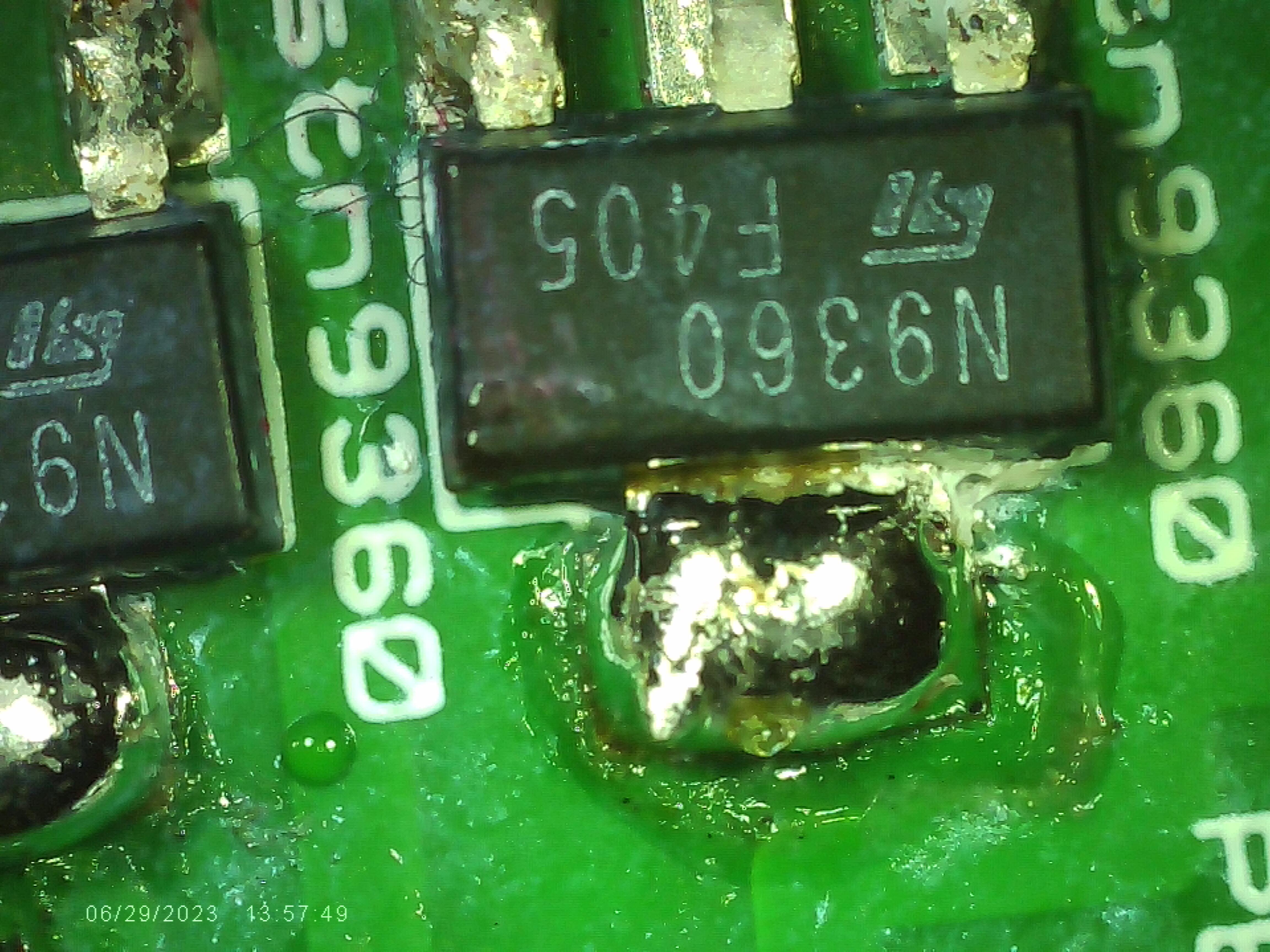
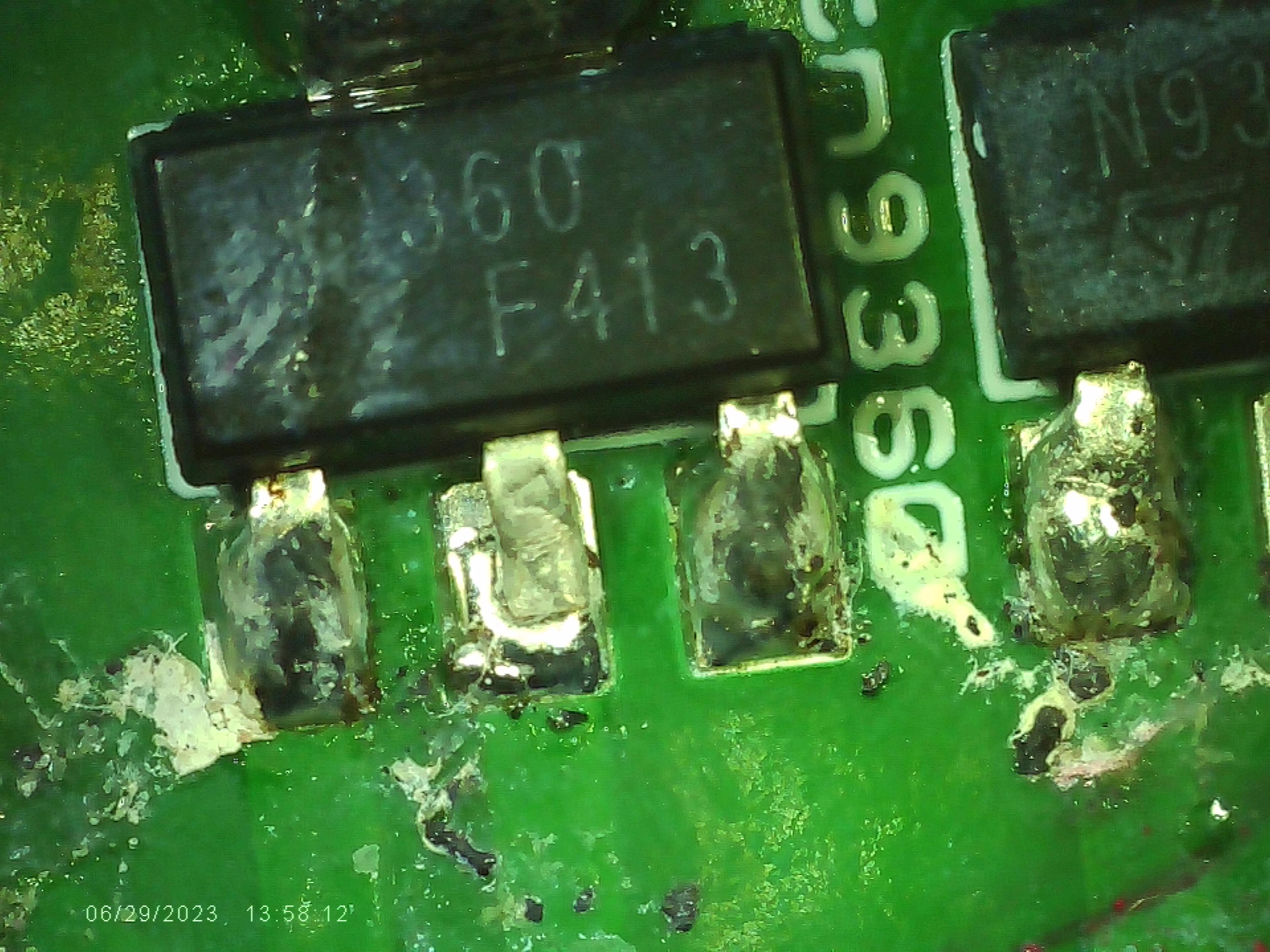
Note, not my soldering job. battery in microscope dead too much work to get the 1:1 lens out.

-
i just looked at what i had in stock. F405 and F413. both work fine. logo looks printed on. not etched and not stamped either.
-
Megatron Electrostatic Headphone Amplifier
kevin gilmore replied to kevin gilmore's topic in Do It Yourself
probably easier to change the cathode resistors on the current sources. -
mauser was legit. went bankrupt more than 10 years ago. they produced firearms. german manufacturer. mouser is definitely legit. never got a fake part from them yet.
-
Megatron Electrostatic Headphone Amplifier
kevin gilmore replied to kevin gilmore's topic in Do It Yourself
so more than a few people are getting clobbered with 300b that don't even come close to the original published western electric document. of the 7 different varieties i have, only the original 1960's manufactured western electric comes even close to the spec. and the new western electric tubes come in low vgk and high vgk versions. (The B series tubes) just means you have to mess with the resistors. and yep its a major pain in the ass. the el34 original version pretty much worked +/- a few volts no matter what tube you stuffed in there as long as they all from the same manufacturer. or build a megatronxxl now known as optimus-prime. more money, but less of a balance problem. -
get yourself a high voltage transistor tester and make an adapter board or solder wires to test subject. in this case it absolutely has to have a breakdown voltage of about 640. but in any case >600 the second part is likely genuine. no one is going to pirate a $1 part. the big hfe change i am beginning to see more and more of.
-
150ma for -60 50ma for -250
-
150ma spec for +/-500 50ma spec for +/-250 150ma spec for -60 50ma for +/-15
-
Megatron Electrostatic Headphone Amplifier
kevin gilmore replied to kevin gilmore's topic in Do It Yourself
quotting shawn "I have some concerns if two modules can work in parallel. In Megatron XL, the two 300Bs per channel share the same filament supply" no they do not. each output tube (all 4 of them) has its own filament supply. they have to be seperate supplies for the 300b because they are in the audio circuit. in the d&g i use 2 switching modules in series to get the equivalent for 10v. -
Megatron Electrostatic Headphone Amplifier
kevin gilmore replied to kevin gilmore's topic in Do It Yourself
so that chassis in various sizes was available on ebay. i do not know whether it is still available. will have to look later. i know that some people think the tent labs filament supply is gods gift to dht tubes. real fact is that it does not really like hanging off -450v. as it was never designed to do so. there are better, cheaper and smaller ways of doing this. -
finally an electrostatic transportable
kevin gilmore replied to kevin gilmore's topic in Do It Yourself
you are aware that you need a heatsink touching all the sot transistor. still with heatsink it typically can take about 5 minutes to reach high temps. -
finally an electrostatic transportable
kevin gilmore replied to kevin gilmore's topic in Do It Yourself
i am aware of the overheating issues. i have an assembled board coming to me to look into this. something clearly has changed from the original parts i used and there is some positive thermal runaway that did not happen with the prototype. there is a later version board now, 4 layers, still does not fix the problem. putting 12v zeners in series with the 1.1meg resistors may introduce enough negative thermal compensation. otherwise the bias needs to be trimmed a lot. hate the parts situation i do. -
Feliks Audio Bliss - so much stupidity...
kevin gilmore replied to spritzer's topic in Headphone Amplification
can't find any internal pictures. but a 6ca7 as a current source for a 300b has plenty voltage swing, more than 1600 volts is possible. but the front end is lacking in voltage gain. so you are definitely going to need one of those 10v output dacs. -
you forgot the dn2540 cascode on the 10m90s