kevin gilmore
-
Posts
7,124 -
Joined
-
Last visited
-
Days Won
21
Content Type
Profiles
Forums
Events
Everything posted by kevin gilmore
-

and now for something completely different part 3
kevin gilmore replied to kevin gilmore's topic in Do It Yourself
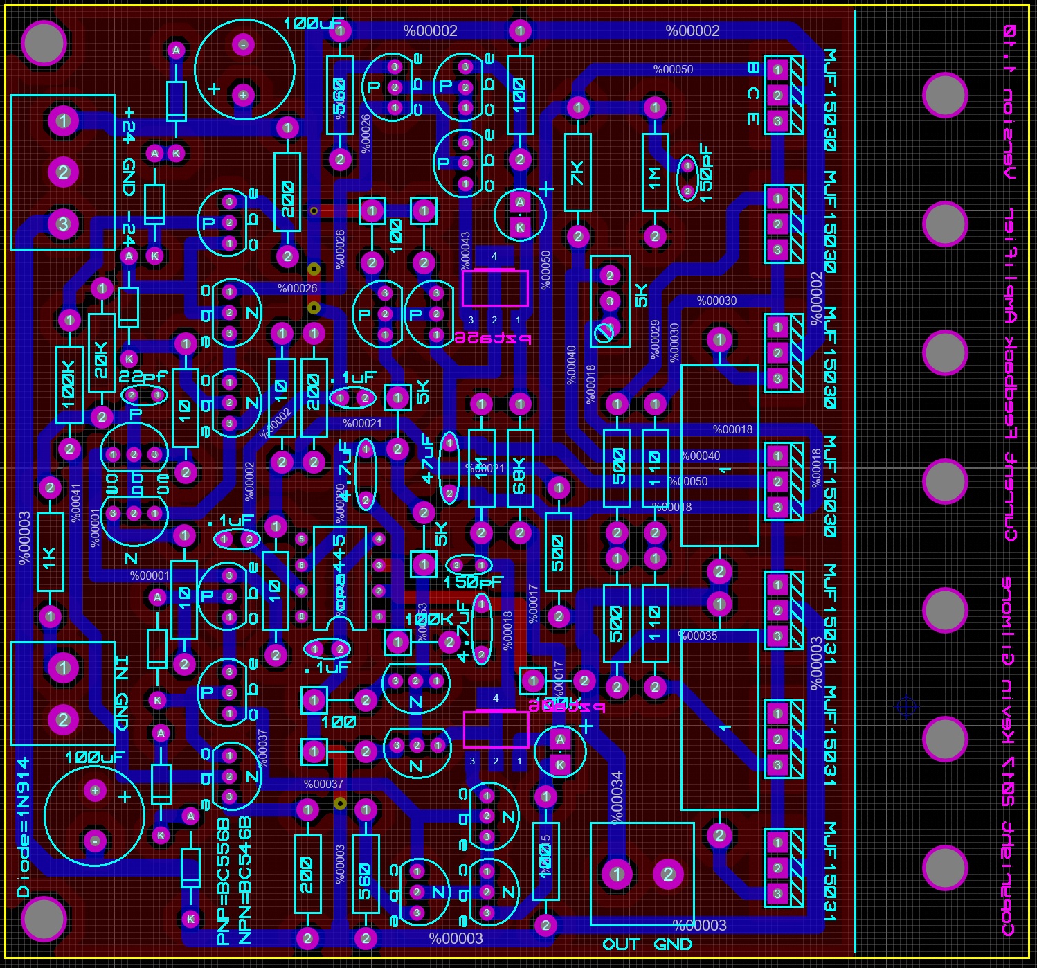
newest version of the current feedback amplifier with the servo not in the audio circuit so that you can use cheaper opamps. But if you run 30v, you still need 30v capable opamp. Like opa551. what the noise difference if any, I don't know yet. cfp2hmt.zip
-
and now for something completely different part 3
kevin gilmore replied to kevin gilmore's topic in Do It Yourself
The ones I used were metal film, don't remember which ones inductive things on outputs are a bad idea -
and now for something completely different part 3
kevin gilmore replied to kevin gilmore's topic in Do It Yourself
that is probably close. ksa5 has a fet input stage. -
and now for something completely different part 3
kevin gilmore replied to kevin gilmore's topic in Do It Yourself
Slight DC offset unless you match input parts. So a whoosh as you turn the knob -
and now for something completely different part 3
kevin gilmore replied to kevin gilmore's topic in Do It Yourself
probably a good idea to use 60V transistors for 30V power supply -
that is a bit too much solder on the tab, but it should be fine
-
and now for something completely different part 3
kevin gilmore replied to kevin gilmore's topic in Do It Yourself
the pair of output transistors run at about 200ma the drivers at about 20ma vbe transistor runs at about 10ma -
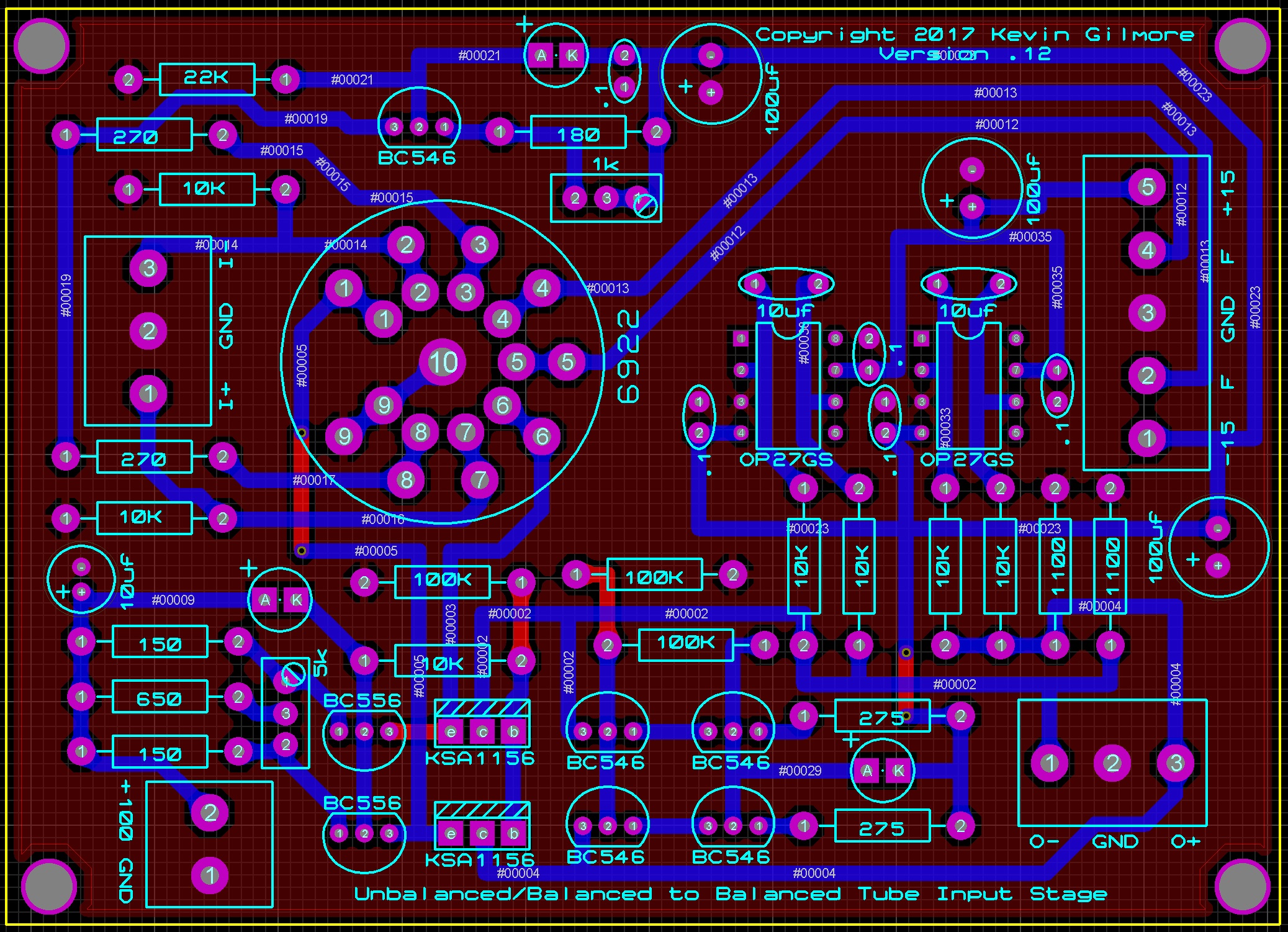
unbalanced/balanced to balanced tube input
kevin gilmore replied to kevin gilmore's topic in Do It Yourself
there are now 2 versions of this, one with the tube on the component side, and the other on the back side for mounting megatron style. ask first. -
and now for something completely different part 3
kevin gilmore replied to kevin gilmore's topic in Do It Yourself
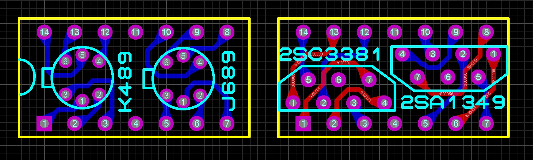
Make sure the toshiba are the matching pinout -
so the bias circuit is constant current into a stack of zeners. 5% or so is all you are going to do with that, and its more than sufficient. what you never want is the voltage swing to exceed the bias voltage. a grlv just for the bias circuit would be massive overkill
-
KG Balanced Dynahi build discussion thread
kevin gilmore replied to Vortex's topic in Do It Yourself
they were the original cascade transistors in the dynahi. can be used as a bipolar input on ssdynalo and ssdynahi. and anything else that has the that340 footprint. also current mirrors for doing servo and a few other things I may come up with. all the fet input options are brutally expensive these days this is another place that has the pins http://www.king-cart.com/phoenixent/product=HEADERS-MACHINED-PIN+BREAKAWAY+.1SP/exact_match=exact -
KG Balanced Dynahi build discussion thread
kevin gilmore replied to Vortex's topic in Do It Yourself
those won't fit in a milmax socket need round pins .018 inch diameter for the socket end -
nope, real product. someone here bought one. maybe originally they had a plan for those 2 extra tubes. I see that the current version has options for dynamic outputs, so maybe the extra tubes have found a use
-
actually there was an electrostatic amplifier made in Canada (mcalister audio) that did just that, 2 extra tubes so that the series filament string came up to the right voltage. the rest of those tubes were not wired.
-
if you populate the cpc1117n part, then you need to apply voltage to turn the power supply on, its normally closed.
-
KG Balanced Dynahi build discussion thread
kevin gilmore replied to Vortex's topic in Do It Yourself
and then things like these for the pins https://www.ebay.com/itm/2-x-2-54mm-Male-40-Pin-Round-Header-Strip-Gold-Plated/161735709722?hash=item25a833141a:g:ehIAAOSw3xJVf2RC i'm sure there is a mouser part number, but can't find it
-
the opto switch is on the grhv power supply boards. You need to drive it with something external. That can be as simple as a switch, or a time delay circuit of any kind, like the one stax uses, or the one on the diy t2 which is 555 timer based etc. Never did a board for that
-
lampizator continues to advertise a DHT Plate Follower with a Voltage gain of +1 with a single triode. Not in this universe. Its crap like that, and transformers secured with double sided tape and a Mikhail class soldering job that tell me to run away fast. 20 years ago when the T2 came out, there was no such thing as a 1600v SicFet. Tubes were then the best way to do high voltages. There is a 4500v SicFet coming soon. Its going to be a bit pricey. But solid state direct drive electrostatic speakers will soon be possible. by the way you do know what birgirs middle name is right?
-
and now for something completely different part 3
kevin gilmore replied to kevin gilmore's topic in Do It Yourself
yes you have to use silicone grease on both sides. or thermasil on both sides for less mess -
and now for something completely different part 3
kevin gilmore replied to kevin gilmore's topic in Do It Yourself
for the grlv, no reason to use the aluminum oxide insulators. the standard ones are just fine and don't make a mess. -
unbalanced/balanced to balanced tube input
kevin gilmore replied to kevin gilmore's topic in Do It Yourself
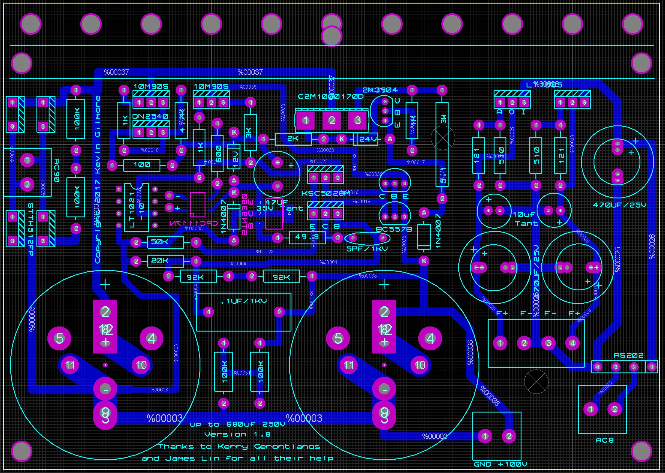
board files for you updated including 100v massive overkill power supply ubaltobaltube.zip grhv100v.zip
-
and now for something completely different part 3
kevin gilmore replied to kevin gilmore's topic in Do It Yourself
this makes me smile a lot -
So I've been looking at a bunch of tube/solid state hybrid dynamic amp schematics, and every one of them is some form of bad, or really bad. (one person/ex company in particular) Low voltage plate, capacitve coupling of a high impedance source into a low impedance, poor balance etc. There had to be a better way. true balanced input. dc coupling. low impedance output. no feedback. proper use of a tube (pure transconducance) etc so I came up with this, work in progress. 4 x 3 inches ubaltobaltubeschem.PDF
- 65 replies
-
- 15
-

-
About 450 usd
-
I was thinking the other board. Yes that board gets that hot due to the transistors you can add heatsinks