kevin gilmore
High Rollers
-
Joined
-
Last visited
Everything posted by kevin gilmore
-
well at least it has a dc protection circuit which the original did not have, and its sure going to need it, absolutely no heatsinking of any kind. OH look, a rail splitter that's necessary because of the ultra cheap single output switching brick. At least its actually built better than the original at less than half the cost. i'll bet that plugging in both unbalanced and balanced headphones is going to cause it to blow up. just like the original
-
it is one board per channel for the tube. your choice of tube front or tube back (different layouts)
-
don't build the DHT one unless you plan on spending piles of cash on tubes
-
I really like that knob
-
845 in a megatron configuration is what you want
-
so the options for the new woo amp 1) plate resistors, they already said its not this 2) inductors, they already said its not this 3) center tapped inductor, you get about 6db of gain with this. 3a) push pull output transformer. all sorts of issues with gain and power with this 4) solid state current source maximum voltage gain of 6sn7 is about 20, maximum voltage gain of 300b is less than 4 somewhere there are likely to be input/interstage transformers and then you are still going to have trouble getting to a voltage gain of 500 or more if you want some feedback to reduce the distortion. the viva evidently is also low on gain, and uses and output transformer. why people produce shit like this I do not know
-
pretty sure it was posted that340.zip
-
That is a 30 amp nema connector.
-
Stax mafia boards linked to in the stax mafia boards thread i highly recommend you doing a diy-t2 as your first amplifier. More than one person has done this. If you survive you will learn a lot less dangerous is the supersymmetry dynalo with the golden reference power supply then the current feedback amp balanced or single ended with the golden reference power supply more challenging is the uber2 amp
-
i'm not sure that the burson like things are going to be good for servo opamps. from what I have seen all of these things are bipolar input and have significant input offset current. Plus they drift with temperature. A low offset jfet input slow opamp is what you want for a servo
-
on the ksa5 the servo's are in the negative feedback loop. So they can influence the sound a little bit.
-
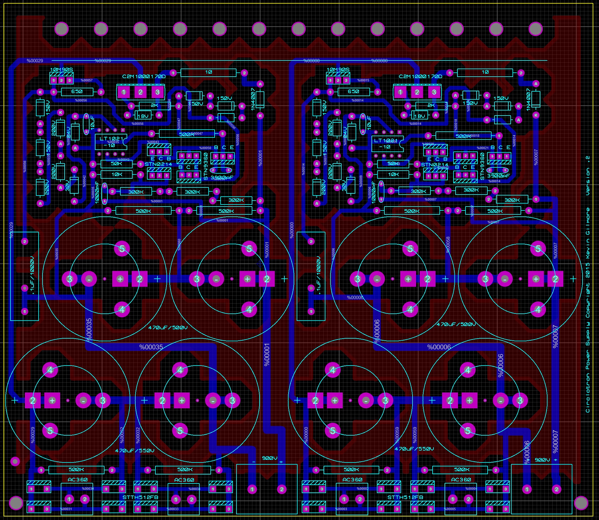
the circlotron boards are 900V
-
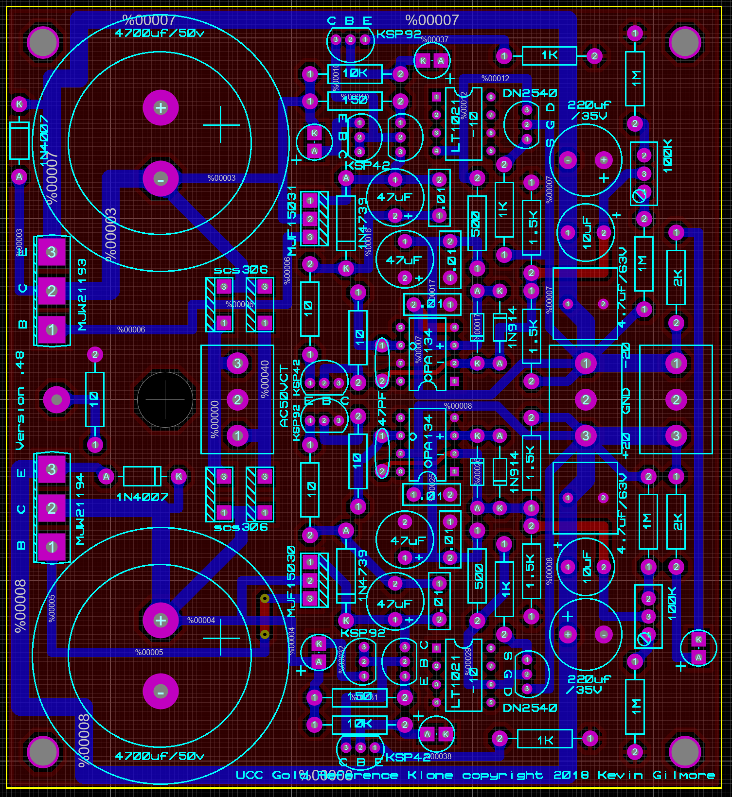
same size board, up to 35mm caps, had to move the pass transistors, needs checking silicon carbide rectifiers 100mm x 109mm goldenreferencelargecap.zip

-
that was for the alps quad pots as I remember
-
The Zener voltage minus 1.4V (darlington) plus about 1 V across the control transistor specifies the minimum output voltage. The zener guarantees enough start up voltage to power up the opamp so something like 8v with a 5v reference
-
The opamp needs to be able to run on what the output voltage is, and the zener plus 1.4V has to be less than the desired output voltage.
-
-
-
-
-
-
-
The 1k input is to prevent oscillations if you short the input to ground. The 20k is in parallel with the bipolar input stage. So the result is something on the order of 10k input impedance. Maybe a bit less.
-
way under a microvolt. pain in the ass to measure.
-
that has to at least double the capacitance of the cable. probably more because the bias wire is no longer shielding the stator wires. stupid fucks.