kevin gilmore
-
Posts
7,131 -
Joined
-
Last visited
-
Days Won
21
Content Type
Profiles
Forums
Events
Everything posted by kevin gilmore
-
 yes I think you are right.
 -
which current limit circuit? on the singles board, to put the ac input on the front requires a size change
-
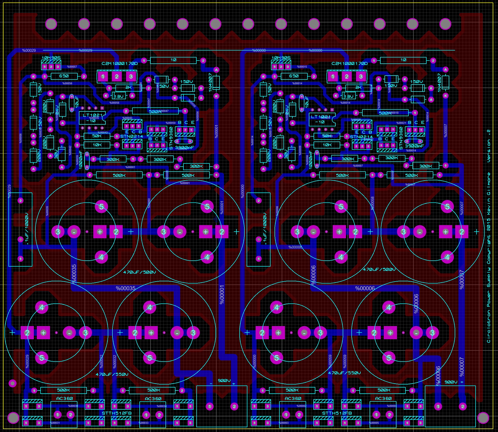
I can certainly do a version with a ground plane. there is no ground on the 900v board, so it would be the entire top side and whatever clearance we decide. say .2 inches here it is without the keepout for the caps and .15 inch clearance

- 256 replies
-
- 1
-

-
- Circlotron
- High Voltage
- (and 1 more)
-
and now for something completely different part 3
kevin gilmore replied to kevin gilmore's topic in Do It Yourself
The 1k input is to prevent oscillations if you short the input to ground. The 20k is in parallel with the bipolar input stage. So the result is something on the order of 10k input impedance. Maybe a bit less. -
goldenreference low voltage power supply
kevin gilmore replied to kevin gilmore's topic in Do It Yourself
way under a microvolt. pain in the ass to measure. -
that has to at least double the capacitance of the cable. probably more because the bias wire is no longer shielding the stator wires. stupid fucks.
-
goldenreference low voltage power supply
kevin gilmore replied to kevin gilmore's topic in Do It Yourself
works fine, more diode switching noise gets thru. Also requires more voltage differential as that current source eats up about 4v. -
[DT-HWT] electrostatic headphone tube Amplifier/Preamplifier
kevin gilmore replied to pham's topic in Do It Yourself
This is yet another attempt to make one amp that does both like the malvalve and RKV. You can optomize for one or the other but not both. -
although you certainly can (singlepower es1,es2...) when you apply high voltage with the tube cold, the cathode can strip. with the diy-T2 applying high voltage with the tubes cold does all sorts of bad to the input tube, putting +500 on the cathode with the filament grounded. soft start on an el34 seems like a waste of time, haven't seen anyone do that. On expensive DHT's, might be a good idea, might be a waste of time.
-
Soft start is one thing, waiting 60 seconds to turn on the high voltage is something else and is a very good idea
-
unbalanced/balanced to balanced tube input
kevin gilmore replied to kevin gilmore's topic in Do It Yourself
so you add a volume control, then 4 of whatever flavor amps you like. -
the T2A round black thing is the fuse, you can check continuity. Looking for exact replacement now 24 volts 1.67 amps mounting holes 3.7 x 1.7 inches made in 2005, so its definitely time to replace this may or may not fit the mounting holes https://www.mouser.com/ProductDetail/Delta-Electronics/MDS-065APS24-BA/?qs=%2fha2pyFaduirkRCGmuVLPGG%2b%2b1Owb2DkcY1eufxPxz01f8scL9gSWw%3d%3d this seems the exact item but its end of life, so maybe buy 2 https://www.mouser.com/productdetail/murata-power-solutions/mvad040-24?qs=sGAEpiMZZMsPs3th5F8koHWdVLP2qW6GCxvvDr00QbM%3D
-
has to be a $25 switcher in there. those things die all the time. Really easy to replace. pics and we should be able to find a replacement. there actually is a fuse on the power supply, looks like a resistor, and if its blown, likely the rest of it is toast, but I have been known to fix them if necessary.
-
goldenreference low voltage power supply
kevin gilmore replied to kevin gilmore's topic in Do It Yourself
you need transformers with higher output voltages. probably custom transformers. -
goldenreference low voltage power supply
kevin gilmore replied to kevin gilmore's topic in Do It Yourself
updated the file. the caps are 25mm -
and now for something completely different part 3
kevin gilmore replied to kevin gilmore's topic in Do It Yourself
Should be just fine -
goldenreference low voltage power supply
kevin gilmore replied to kevin gilmore's topic in Do It Yourself
here is the version with the to220 sic diodes, someone really needs to check this goldenreference6drflipto220.zip -
goldenreference low voltage power supply
kevin gilmore replied to kevin gilmore's topic in Do It Yourself
because soren is running the grlv supply at 4.5 amperes, here is a new version with the feedback resistor locations flipped so that the sense is not one inch away from the output connector. sense is now tied directly to the inner power supply connector. So the 20mv change in voltage due to current should be completely canceled out. for higher currents, best if the board is made with 3 oz copper. goldenreference6drflip.zip -
He is anything but grumpy these days. Probably there are 2 reasons.
-
goldenreference low voltage power supply
kevin gilmore replied to kevin gilmore's topic in Do It Yourself
can't do 5V. best you can probably do is 12V and then you still have to change the reference to a 5V reference check C3 to make sure its not in backwards -
goldenreference low voltage power supply
kevin gilmore replied to kevin gilmore's topic in Do It Yourself
check the values or r9 and r10, it looks like everything is working right if both input pins of the opamp are at -10v -
goldenreference low voltage power supply
kevin gilmore replied to kevin gilmore's topic in Do It Yourself
BOM for the GRxx boards GR79.csv GR78.csv By the way, linear technology is now owned by analog devices, and you can buy these parts from mouser. -
goldenreference low voltage power supply
kevin gilmore replied to kevin gilmore's topic in Do It Yourself
Looks close to the original dual board but bigger. I did not verify the wiring. -
goldenreference low voltage power supply
kevin gilmore replied to kevin gilmore's topic in Do It Yourself
with the opa134 you are limited to 36v. you can certainly change that opamp to opa445 and then it would work up to higher voltages. going to check on the ratings of the transistors now edit: subject to the voltage ratings on the capacitors, so probably 35v -
goldenreference low voltage power supply
kevin gilmore replied to kevin gilmore's topic in Do It Yourself
from Kerry, the gr78xx and gr79xx board files I want a few of each if there is going to be a group buy GR79xx.zip GR78xx-v1-2.zip