kevin gilmore
-
Posts
7,124 -
Joined
-
Last visited
-
Days Won
21
Content Type
Profiles
Forums
Events
Everything posted by kevin gilmore
-
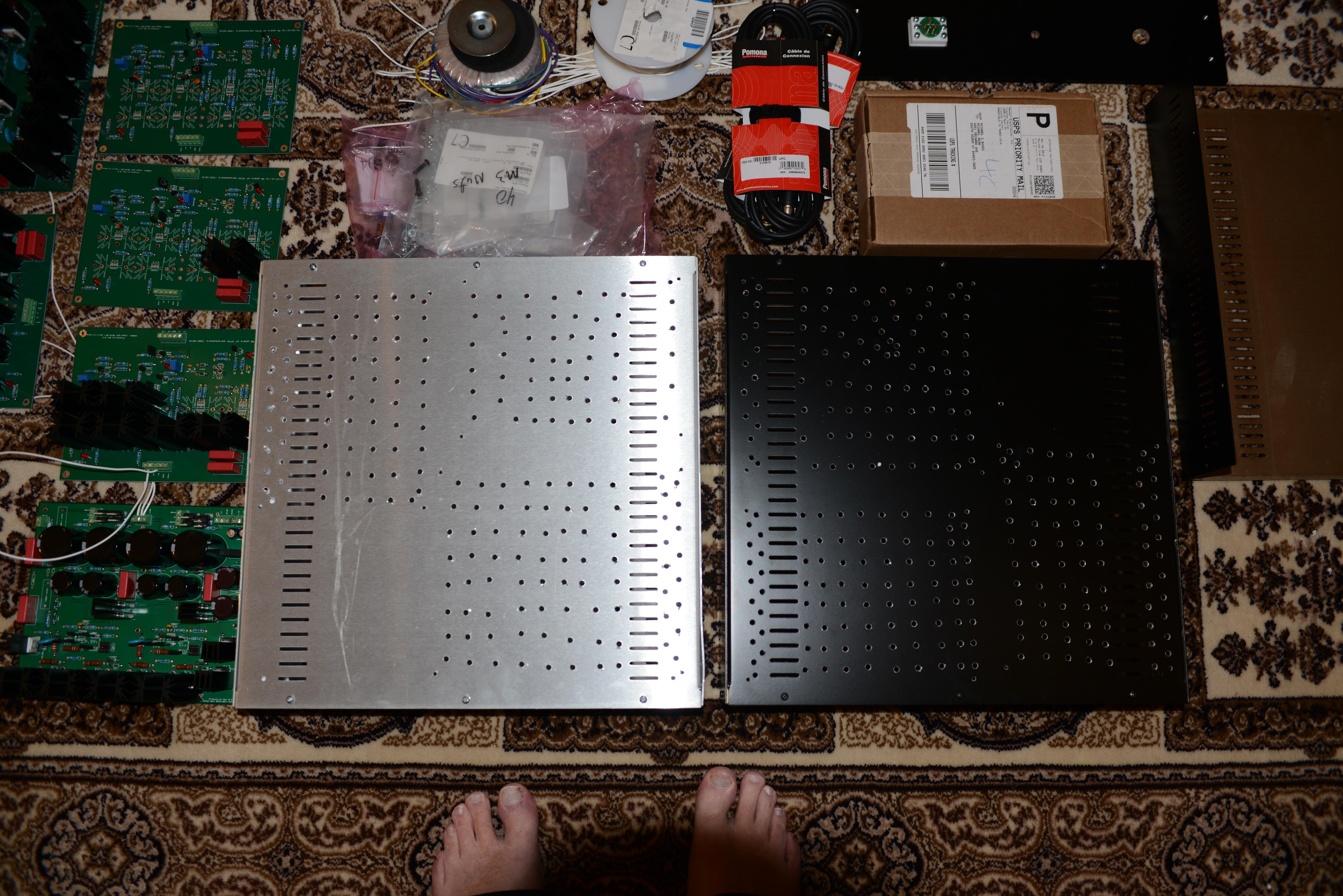
the power board I posted is the original board designed to fit into the vertical fin chassis. my original design for the t2. the other boards were done by joamat. sure looks like they will fit into that chassis.
-
I did the same thing machining from aluminum, the 2 bends for all the heatsink mounted transistors. impossible otherwise. here is a version of the shrunk amplifier board that has been netlisted and teardrop'd. someone would have to check this carefully before making boards. updated file, I think I got them all. t2shrunknet - CADCAM.ZIP staxt2powershrunknet - CADCAM.ZIP
-
The latest gerber files posted above are the same as I sent to kytuphicanh missing trace fixed, rounded corners and gerber v2. It would take a whole bunch of time to netlist the board which would allow filleting. Current board works, so I will leave it alone.
-
updated shrunk board files with missing trace fixed and rounded corners staxt2powershrunk.ZIP t2shrunk.ZIP
-
if they used dermabond to glue you back together, most of that will disappear. If they sewed you up, it will look that way for a very long time.
-
I think I sold the complete chassis with angle brackets and board set for $1295, but I was not making any money. (no sand) one more for posterity. Really like this one, definitely takes talent to do this.

-
reposted for posterity. Any person that would do this and think they can assemble a T2 probably should reconsider.
-
I don't know who that is, but the angle brackets are nowhere in any of those pictures. Almost impossible to build without the angle brackets. and brazilnut is aka hennyo aka dude5OO aka becky aka rebecca aka... so I would not put much value in what he says.
-
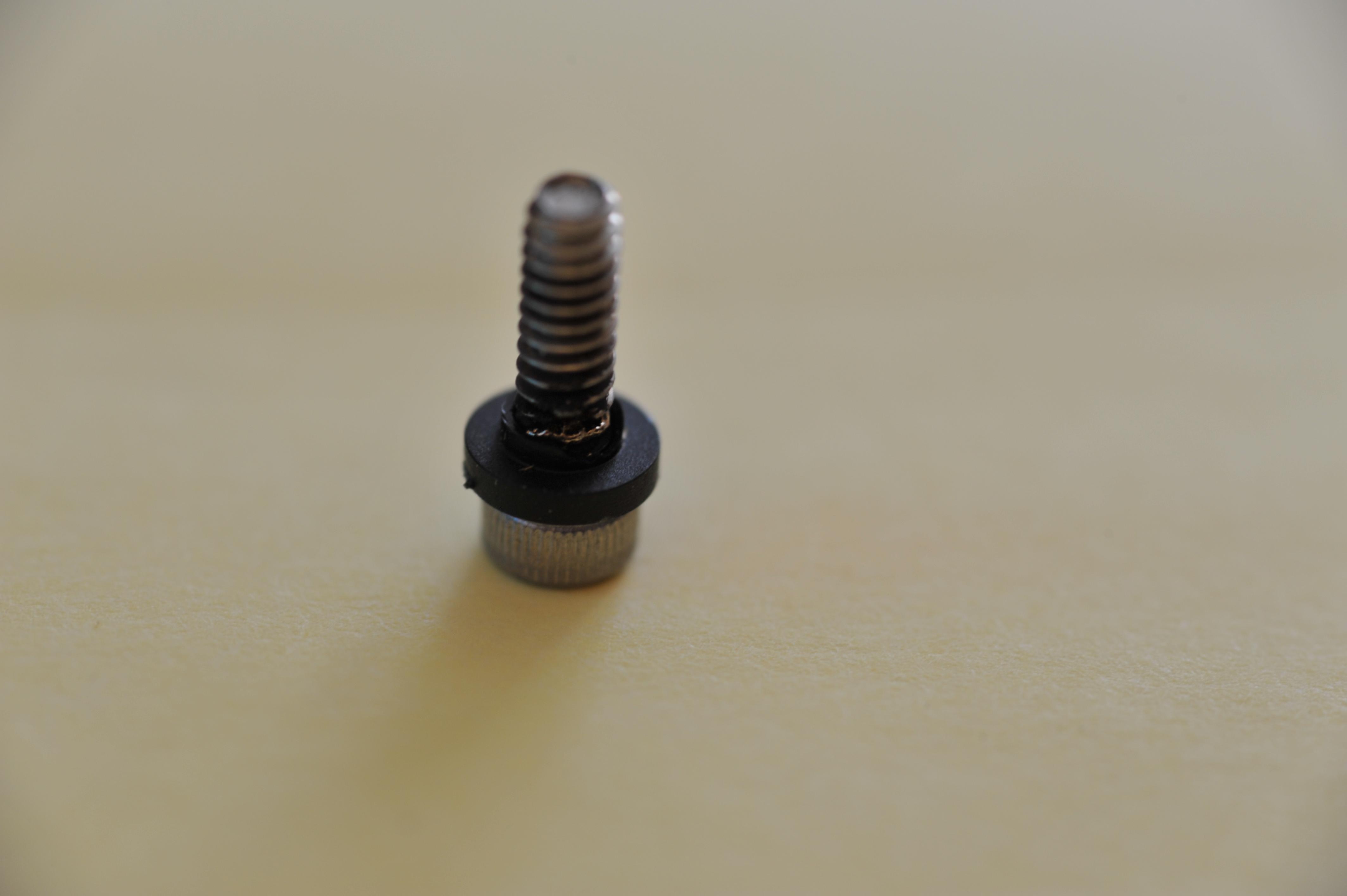
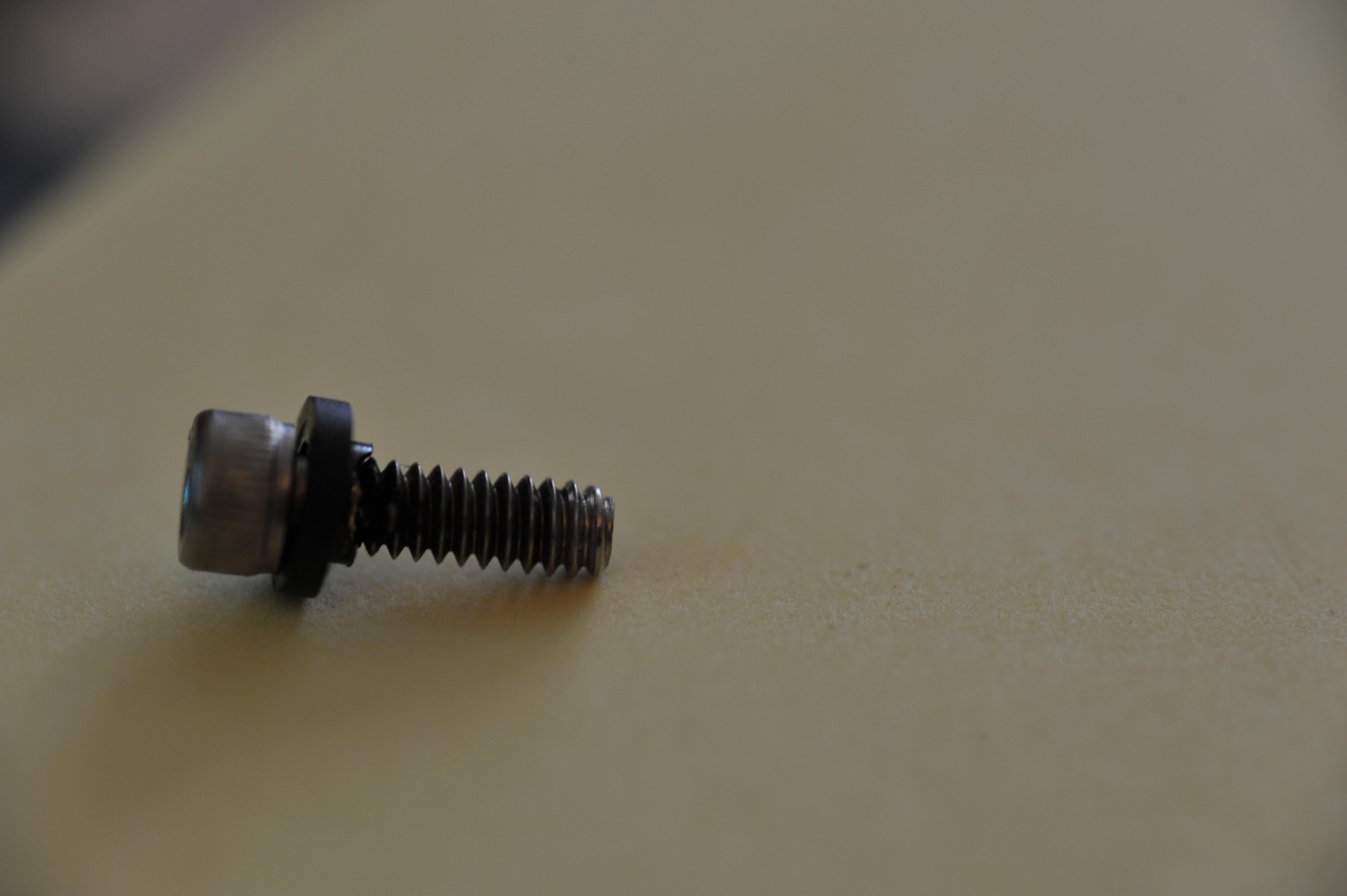
so here are 2 pictures of the screw being arc'd material from the screw is missing and the plastic is melted These are from the T2 power supply and the voltage was close to 600V
- 35 replies
-
- 1
-

-
- stax
- kevin gilmore
- (and 3 more)
-
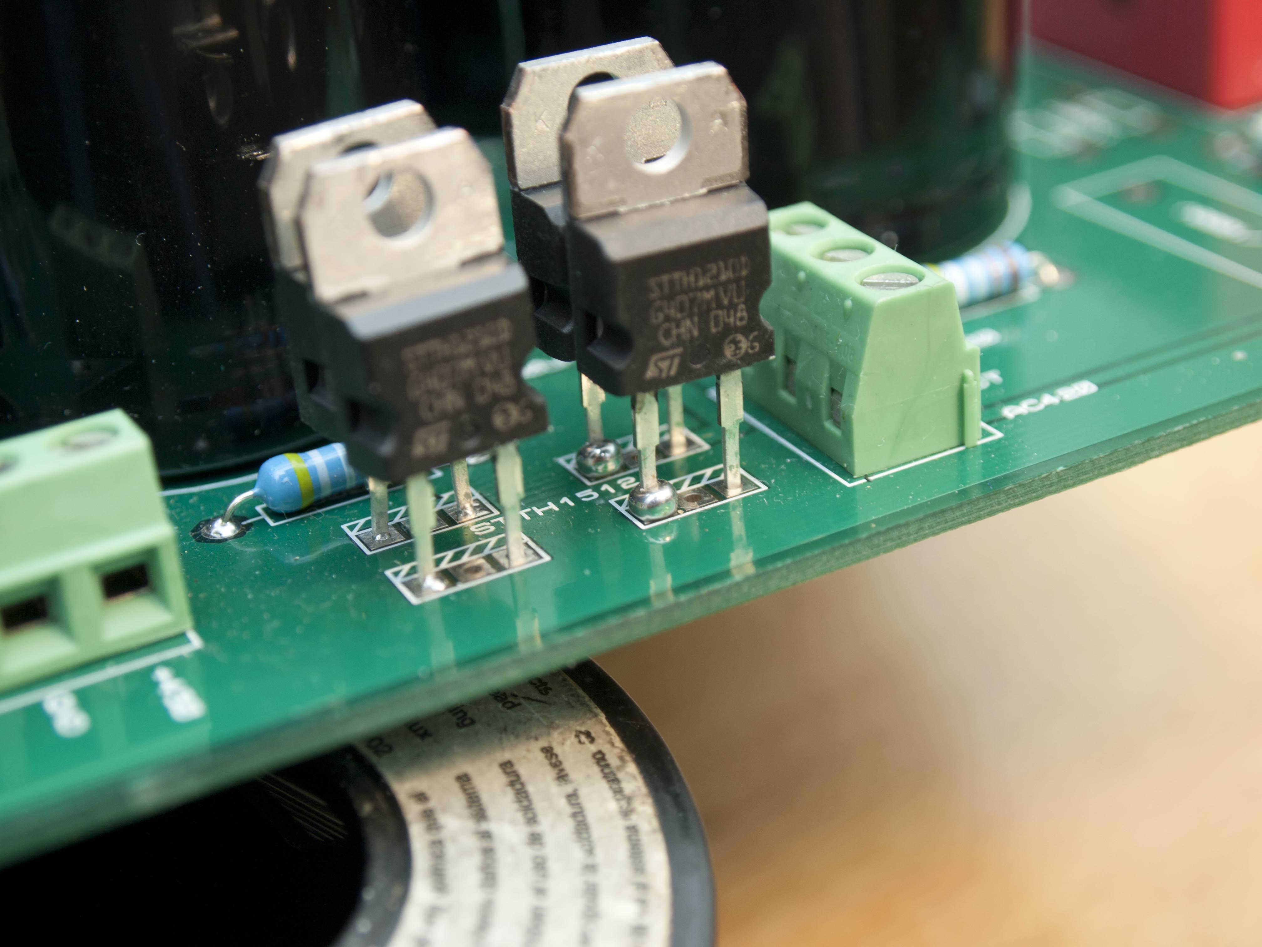
I do have a picture of the t2 arcing, it was thru the screw to the center hole. After that most of us switched to ceramic and peek or similar screws. It's actually only 350v in this case, B+ to ground.but still, likes to arc. The thicker silpads without holes and spring clips also work but you have to drill extra holes in the heatsinks. 5.1k. Rn60d resistors is what most people use. i forgot about the bias line, should be 4.7M (or 5M) rn60d. Required for sr007,sr009 i might be able to add the 5.1k resistors to the board
- 35 replies
-
- 1
-

-
- stax
- kevin gilmore
- (and 3 more)
-
The intent was to attach the board to the side with the heatsinks vertical using these or similar. Board down, or Board up, really does not matter. http://www.newark.com/ettinger/14-86-313/mounting-bracket-steel-enclosures/dp/59M4493?ost=14.86.313&ddkey=http%3Aen-US%2FElement14_US%2Fsearch
- 35 replies
-
- 1
-
-
- stax
- kevin gilmore
- (and 3 more)
-

Megatron Electrostatic Headphone Amplifier
kevin gilmore replied to kevin gilmore's topic in Do It Yourself
then you need to lower the resistance of r11 even further. -
Megatron Electrostatic Headphone Amplifier
kevin gilmore replied to kevin gilmore's topic in Do It Yourself
something is wrong, with .85ma and 300v, should be 240 volts that is only 20 volts now to B+, the stage is likely to clip -
goldenreference low voltage power supply
kevin gilmore replied to kevin gilmore's topic in Do It Yourself
Same pinout so they should work -
feedback is absolutely not going to work, need resistors between cathodes and R3. But then the gain goes down And then you need C2. And there is not enough voltage gain to begin with.
-
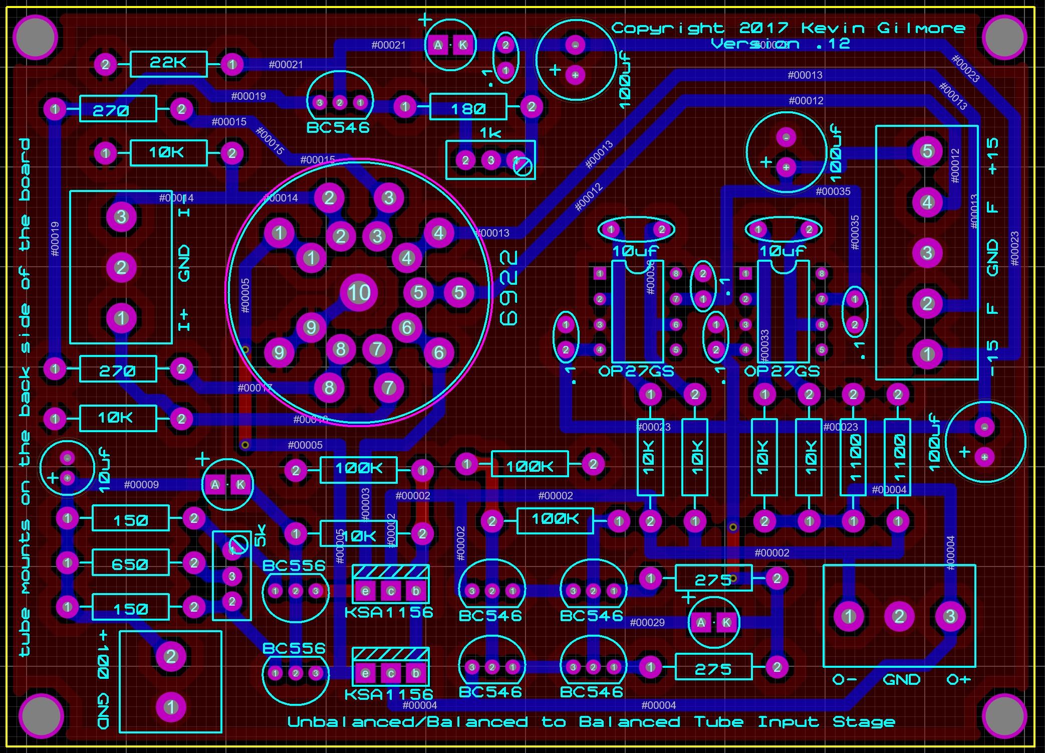
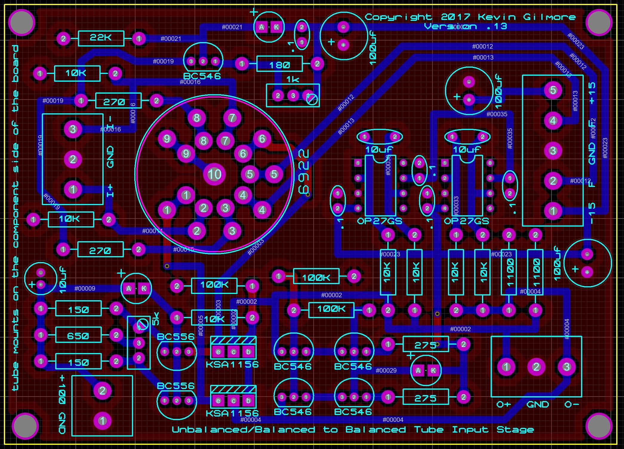
unbalanced/balanced to balanced tube input
kevin gilmore replied to kevin gilmore's topic in Do It Yourself
here are both of them, not sure which one was in the group buy 3) Its a current mirror. So output voltage depends on impedance, currently 1100 ohms. Needs an output buffer if you are going to use it for a preamp.
-
the Teflon drifts a bit. So the diameter is .716 inch and the hole size is 81th have not found a socket that does not fit or fits tight yet.
-
goldenreference low voltage power supply
kevin gilmore replied to kevin gilmore's topic in Do It Yourself
no room for anything else... -
dual primaries are fine everywhere in the world except japan.
-
yes they definitely work. where the schematic is, not sure at the moment. if there are troubles its usually the that340 chip.
-
All the SumR transformers I bought were universal voltage. 100,120,200,240 dual windings, one tap per winding They should already know exactly what these transformers are. It would probably take me a while to dig up the original quotes.
-
ksc5026 is an in stock substitute for the npn
-
that is amb's step attenuator setup and should be fairly easy to fix.
-
It really depends on which resistors were changed. If they gave you a schematic, please post it. Edit: found the schematic. you can replace the 1k with 10k resistors. The power supply will come up a bit slower, but it will otherwise work.
-
Yes that is one of my layouts, not in a position to look up schematic/board at the moment.