kevin gilmore
-
Posts
7,110 -
Joined
-
Last visited
-
Days Won
21
Content Type
Profiles
Forums
Events
Everything posted by kevin gilmore
-

goldenreference low voltage power supply
kevin gilmore replied to kevin gilmore's topic in Do It Yourself
much better. max sensitivity of the qa403. 60 hz and multiples are very hard to remove, moving wires around in the box and things will change. completely inaudible. the synchronous rectifiers may take out even more noise. mumetal shielding around the transformer is also a good idea. glad that more and more people are buying the qa403. higher quality diy coming soon -
goldenreference low voltage power supply
kevin gilmore replied to kevin gilmore's topic in Do It Yourself
might want to try again with a good quality mylar cap say 1uf in series with the power supply outout. you should be able to get better resolution. -
need to see the whole board. definitely missing the power supply caps at the lm339
-
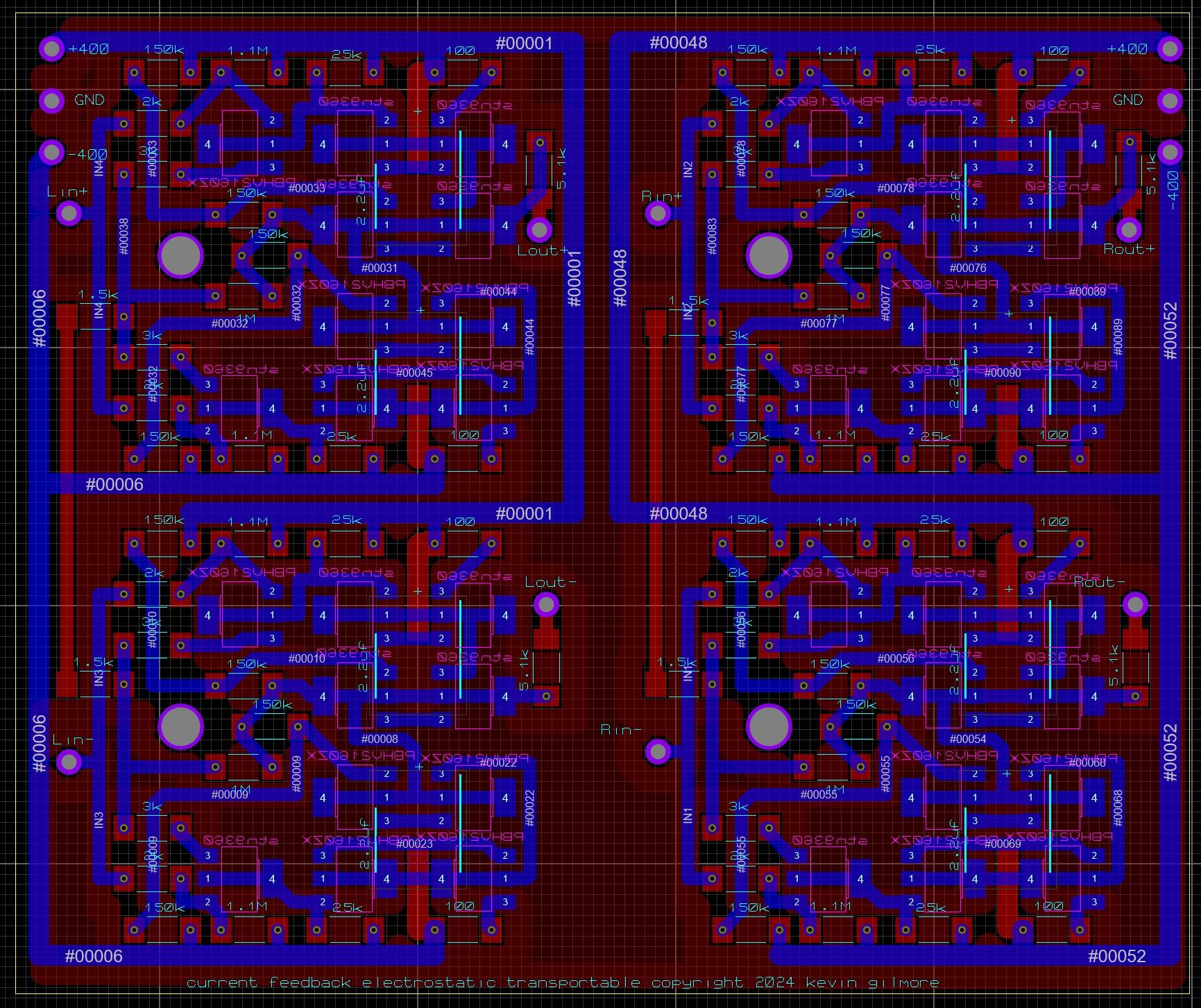
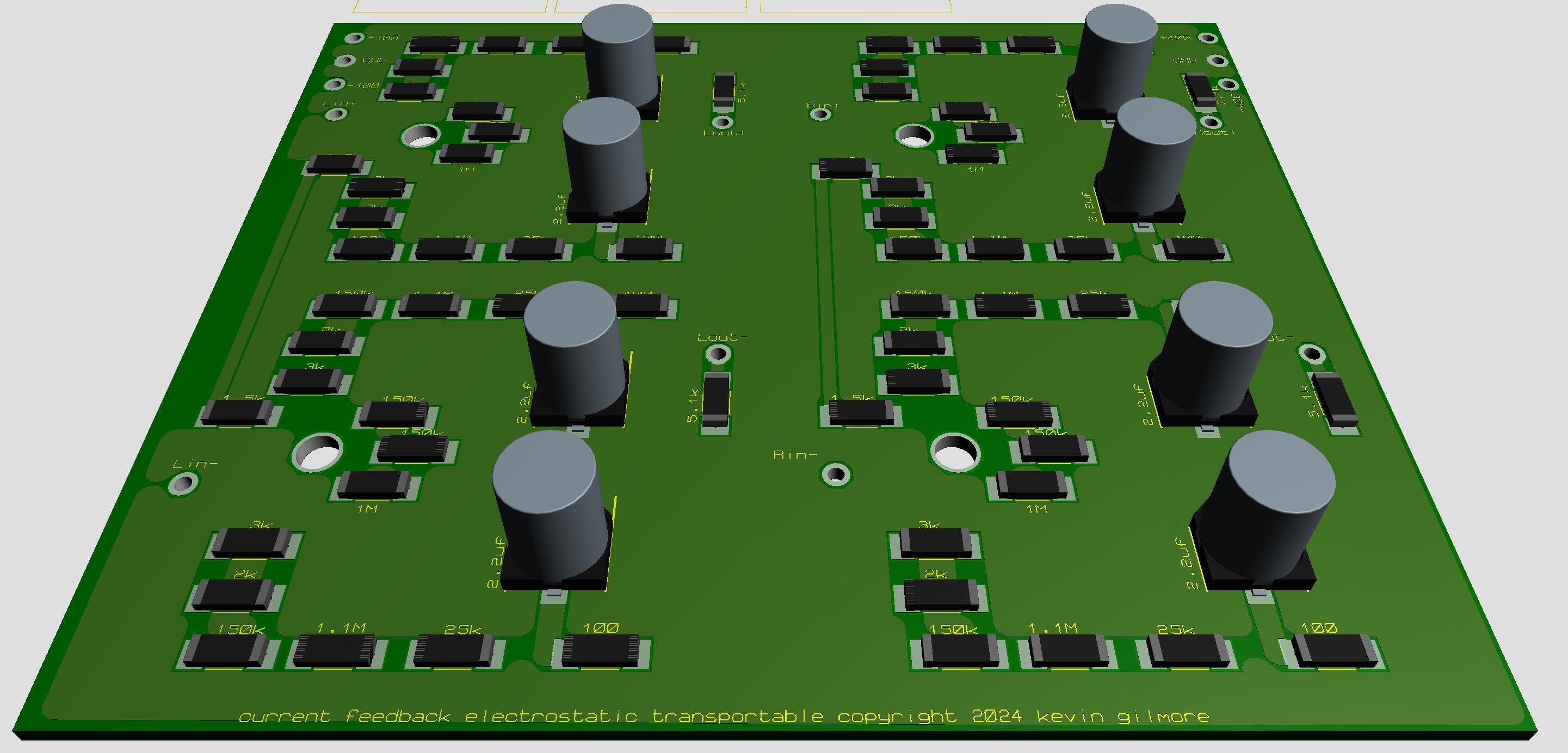
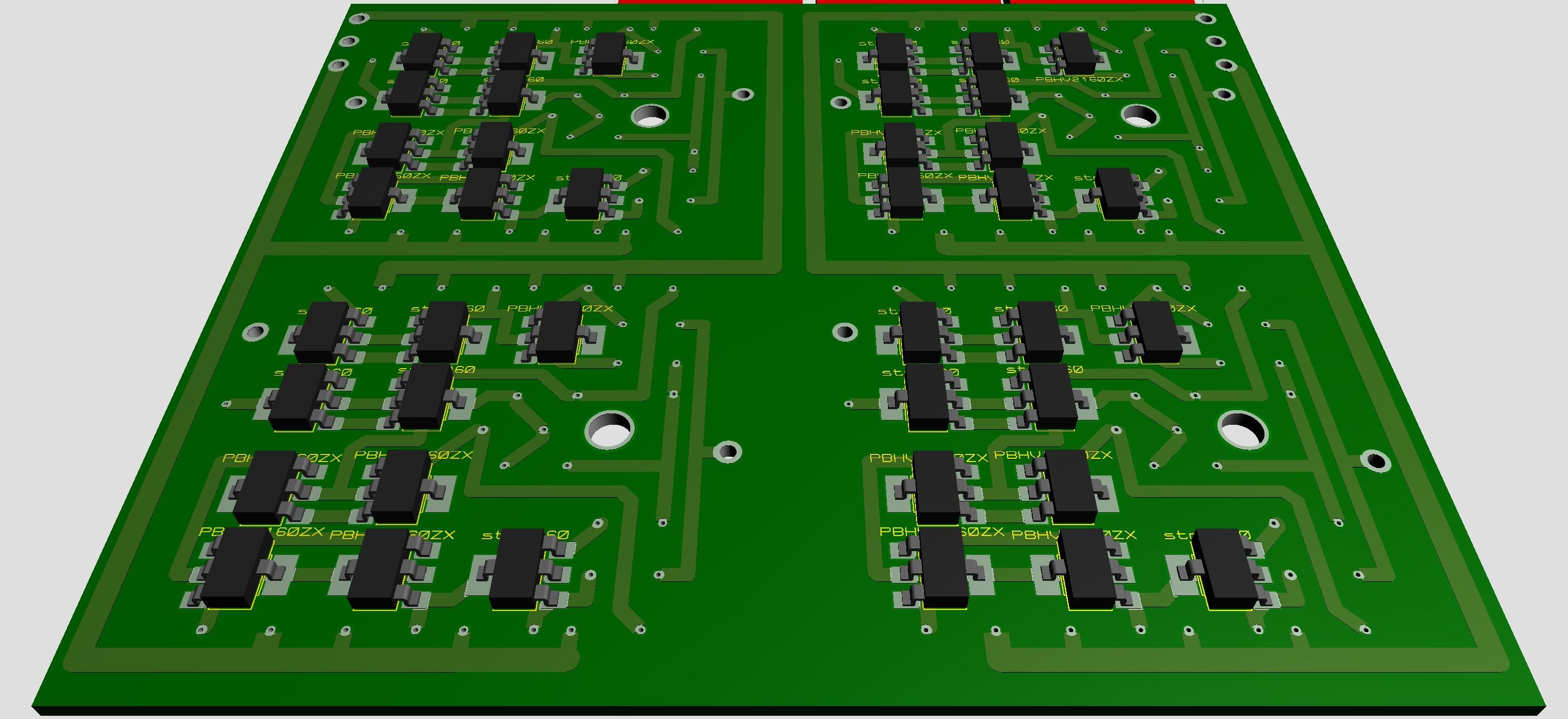
finally an electrostatic transportable
kevin gilmore replied to kevin gilmore's topic in Do It Yourself
pretty close to production now.
-
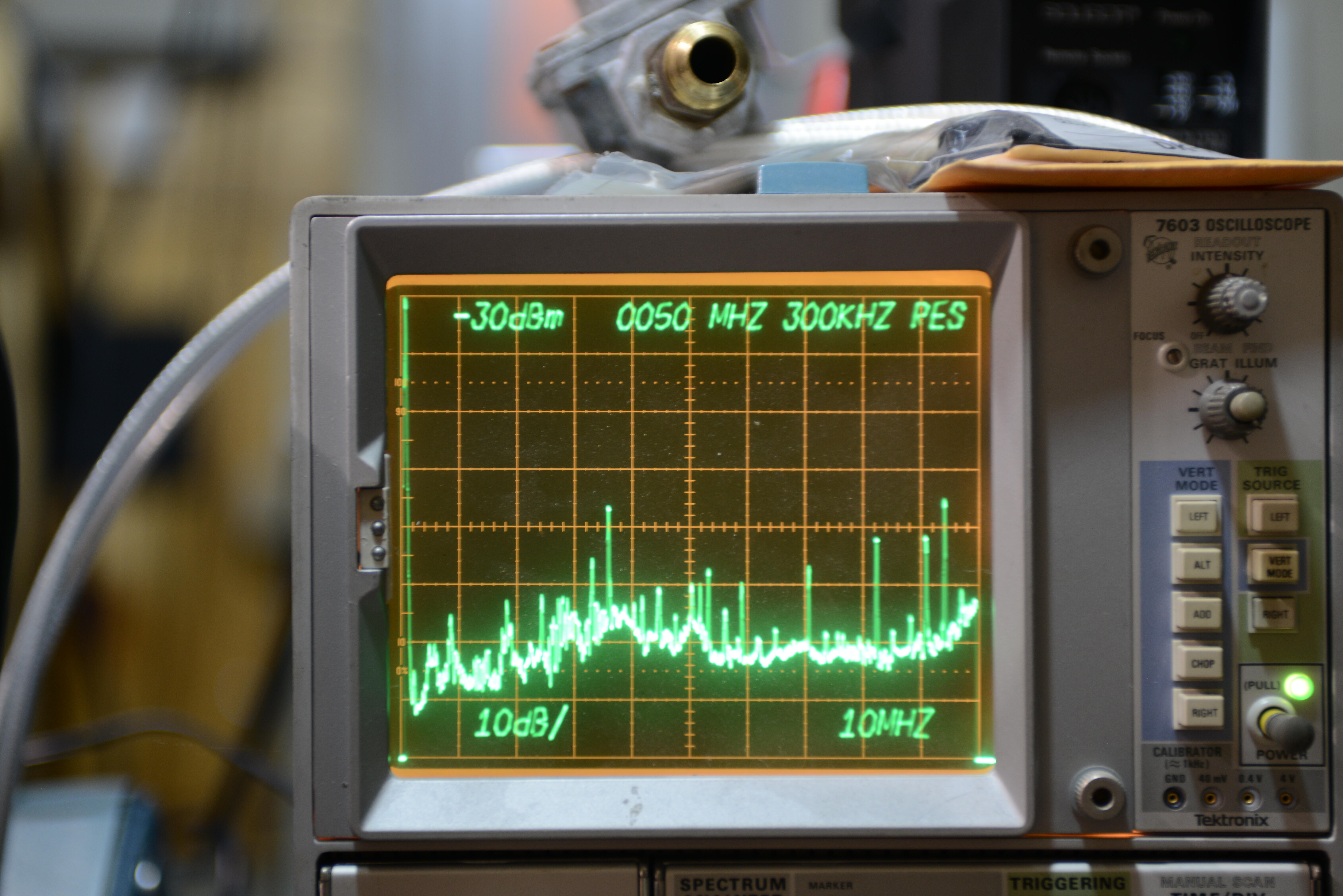
finally an electrostatic transportable
kevin gilmore replied to kevin gilmore's topic in Do It Yourself
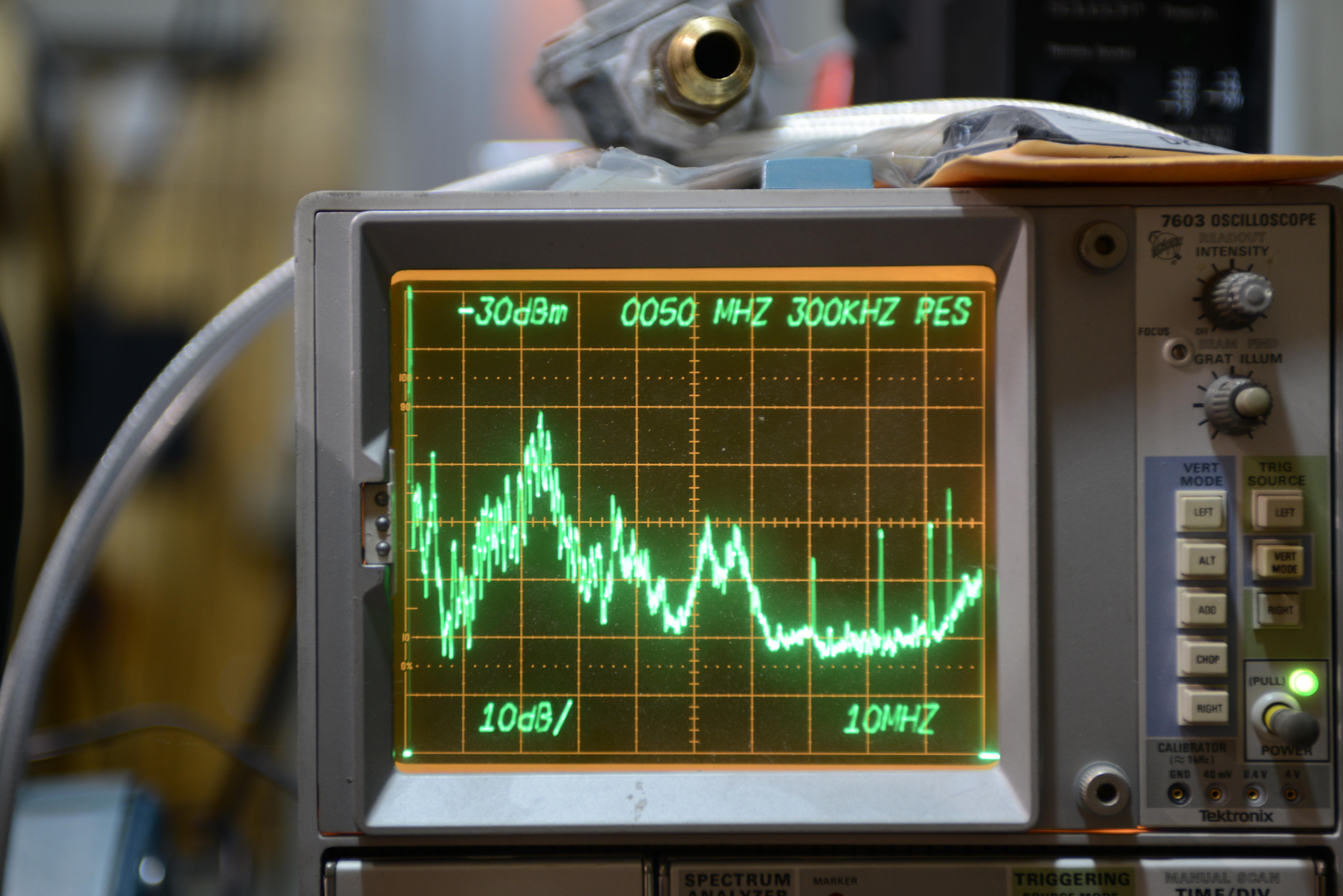
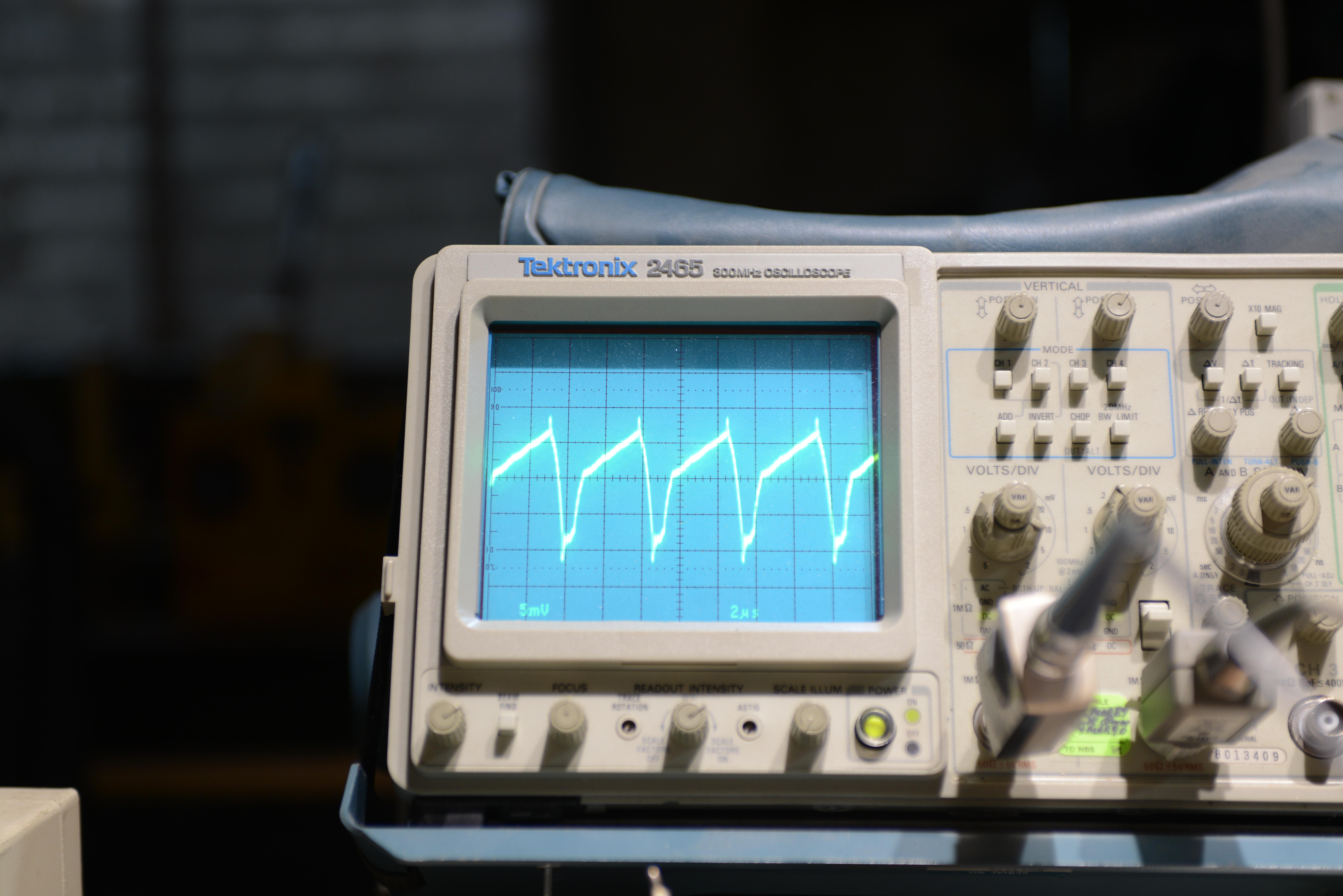
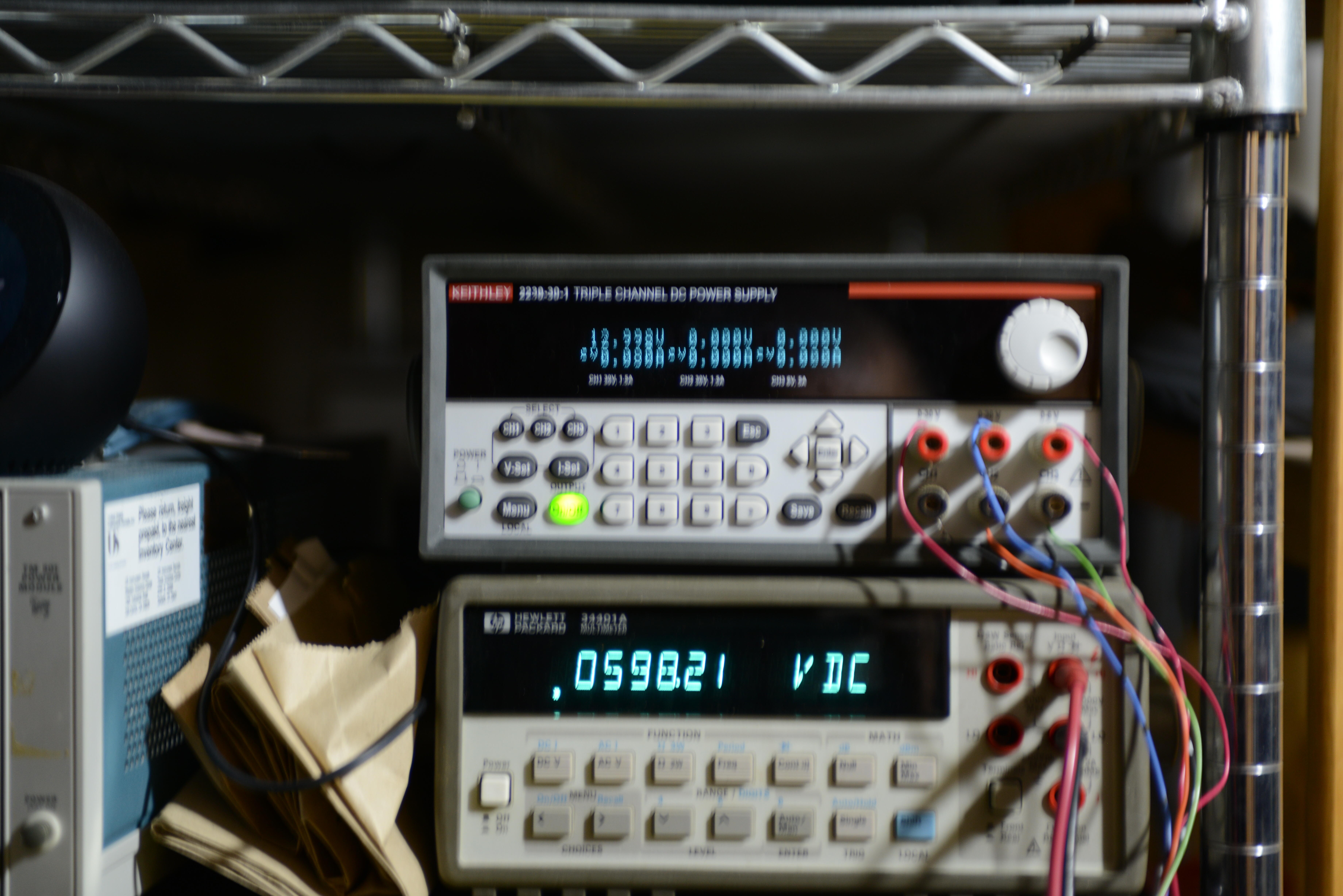
first picture is baseline with 6db antenna 0 to 100mhz 10db/major division 10mhz per horizontal major division top line -30dbm 1 inch from power supply. second picture is with the 600v power supply turned on and into a 1meg ohm load. 3rd picture is hall probe on the input power supply line. so 200khz flyback switching frequency.
-
finally an electrostatic transportable
kevin gilmore replied to kevin gilmore's topic in Do It Yourself
i did some quick tests and they are pretty quiet. but i plan on doing more exact tests. cap.inductor,cap should be more than enough. spec sheet seems to imply 20mhz which cant be right. will get out the spectrum analyzer to make sure. -
finally an electrostatic transportable
kevin gilmore replied to kevin gilmore's topic in Do It Yourself
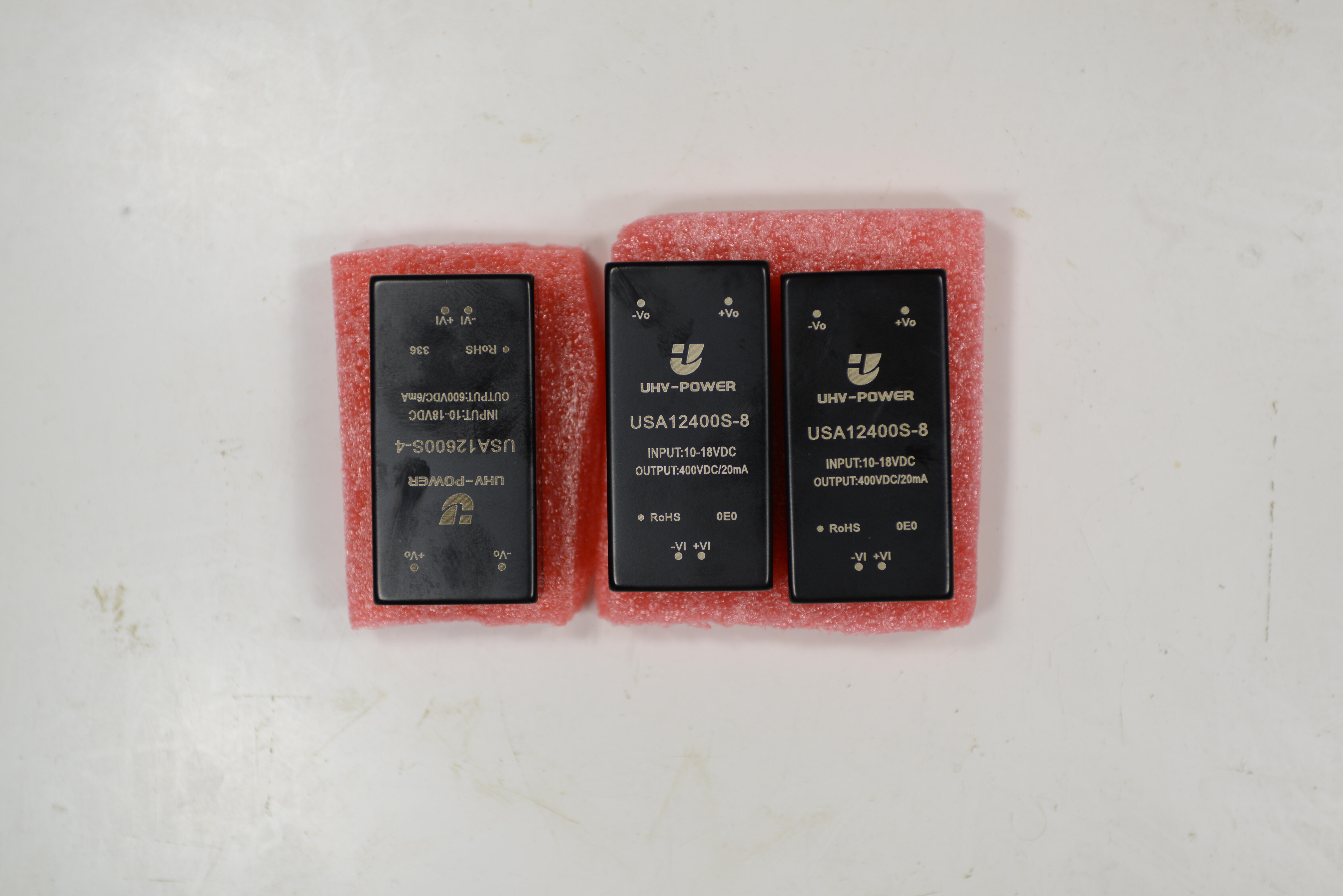
all three power supplies a total of $80.62 with shipping from china. fully regulated 12v to 18v input. i could not build these things for that price, no way.
-
after all these years we have finally found a solution for the power supply modules at a rational price. which means we can make a transportable electrostatic amplifier. similar to srmxh,srm252,srm270 etc. 3 times the power, +/-400v power supplys, no obsolete components etc. designed to be mounted to the bottom as a heatsink with silicone thermal sheet in between. should be about $250 in parts unless you go nuts with the volume pot. not sure of casing yet.
-
and now for something completely different part 3
kevin gilmore replied to kevin gilmore's topic in Do It Yourself
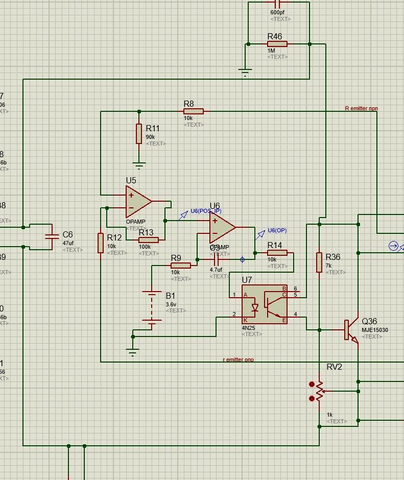
so this is the way to do it correctly. its the only way not to seriously effect the thd. unfortunately both opamps have to take the voltages of the output devices. which means they have to be opa445 you set rv2 to the maximum amount of current. Then B1 is a 10k pot to V+ and ground. r11 is actually 100k.
-
and now for something completely different part 3
kevin gilmore replied to kevin gilmore's topic in Do It Yourself
if it works right then yeah. -
and now for something completely different part 3
kevin gilmore replied to kevin gilmore's topic in Do It Yourself
would like to see what effect this has on thd. especially large voltage swings. still think an optoisolator drive to the vbe multiplier. -
totally 100% safe. looks like about 100kva. proper personal protective equipment required. typically 600v if its to generate 3 phase. makes the stuff birgir is doing to e-cars look tame.
-
its all stax tube amp with mills style non-inductive plate resistors. thats basically all of them except for the t2.
-
suggest you solder all connections associated with the filaments. and then solder them again.
-
someone needs to post very high resolution images of front and back, then will correct schematic if necessary
-
suggest you redraw that part of the schematic that you think is wrong. there have been mistakes in stax schematics in the past. especially the t2. once it enters production and works...
-
-
so single stator headphones. like beveridge speakers, but done horribly wrong. 2000v bias. single supply ac coupled 450v with dual in parallel bsp135 as current sources, with dual bsp125 in parallel driven by opa1642 dual opamp. without it being on your head, no seal for the diaphram. lots of dsp to equalize this mess. all analog input signals digitized and then stuffed into the dsp. another example of stupidass (tm&c) engineering. these people should get together with the engineers that did the eha5. so much engineering money wasted. edit: no dsp found.
-
does look like the same amp. however the quality of the western electric tubes with all that fluorescence on the glass is definitely worrying me, clearly they are not pumping down the tubes enough. or not enough getter.
-
there will be 4 output boards. 12 x 6 inch each. filament boards will stack on them, each filament board will have 5 x 5v 4a switchers. 2 switchers in series for the 211 so chassis is likely to be a bit over 24 inches wide and 20 inches deep. updated picture
-
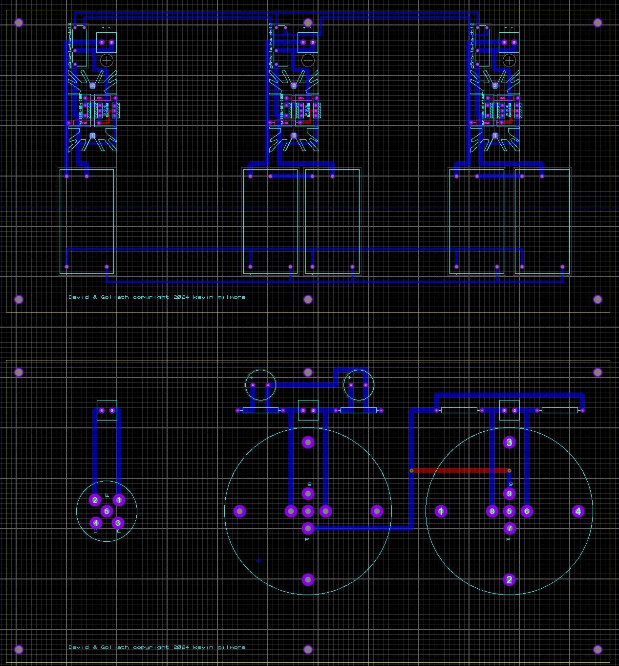
i like that. i also like "david and goliath"
-
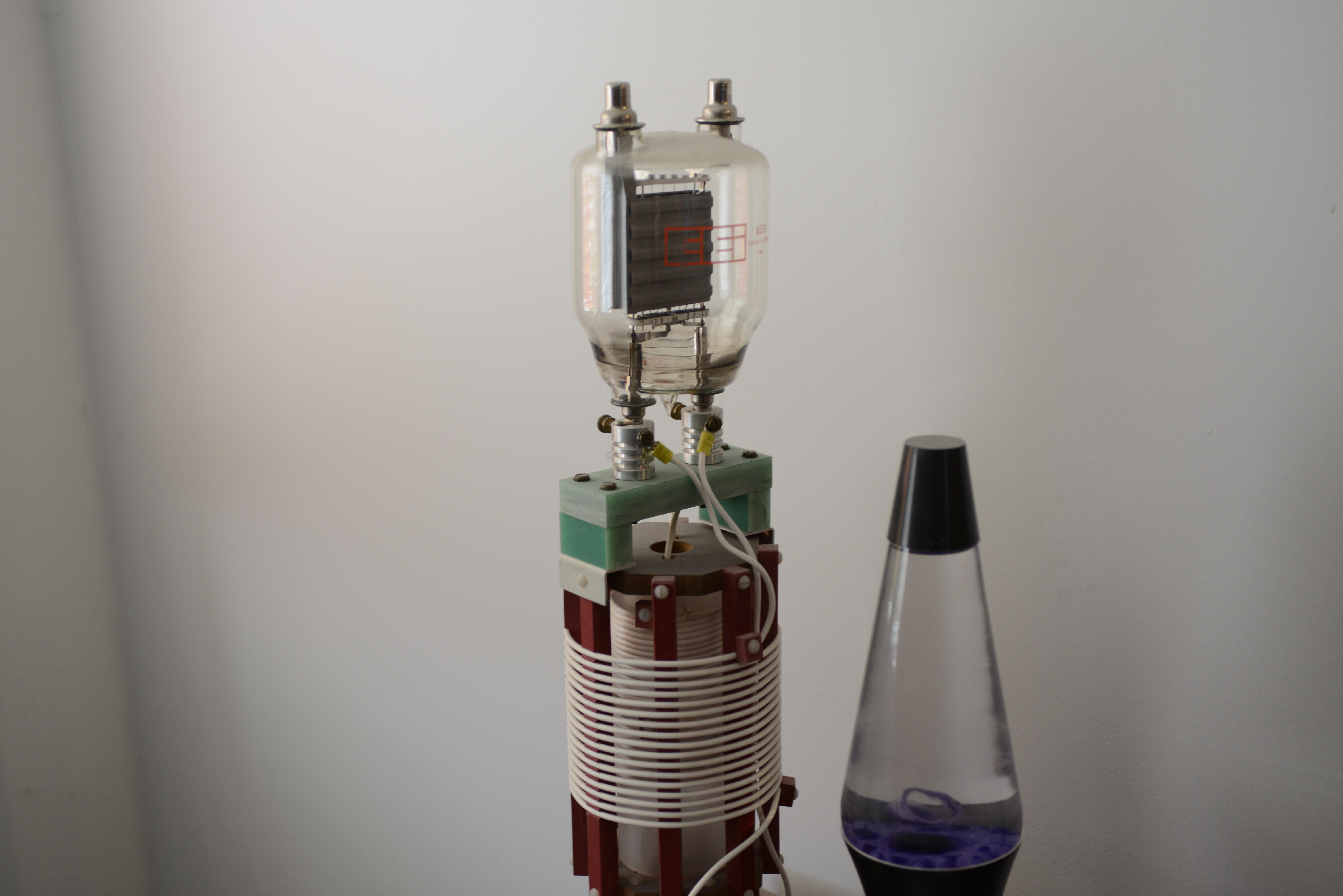
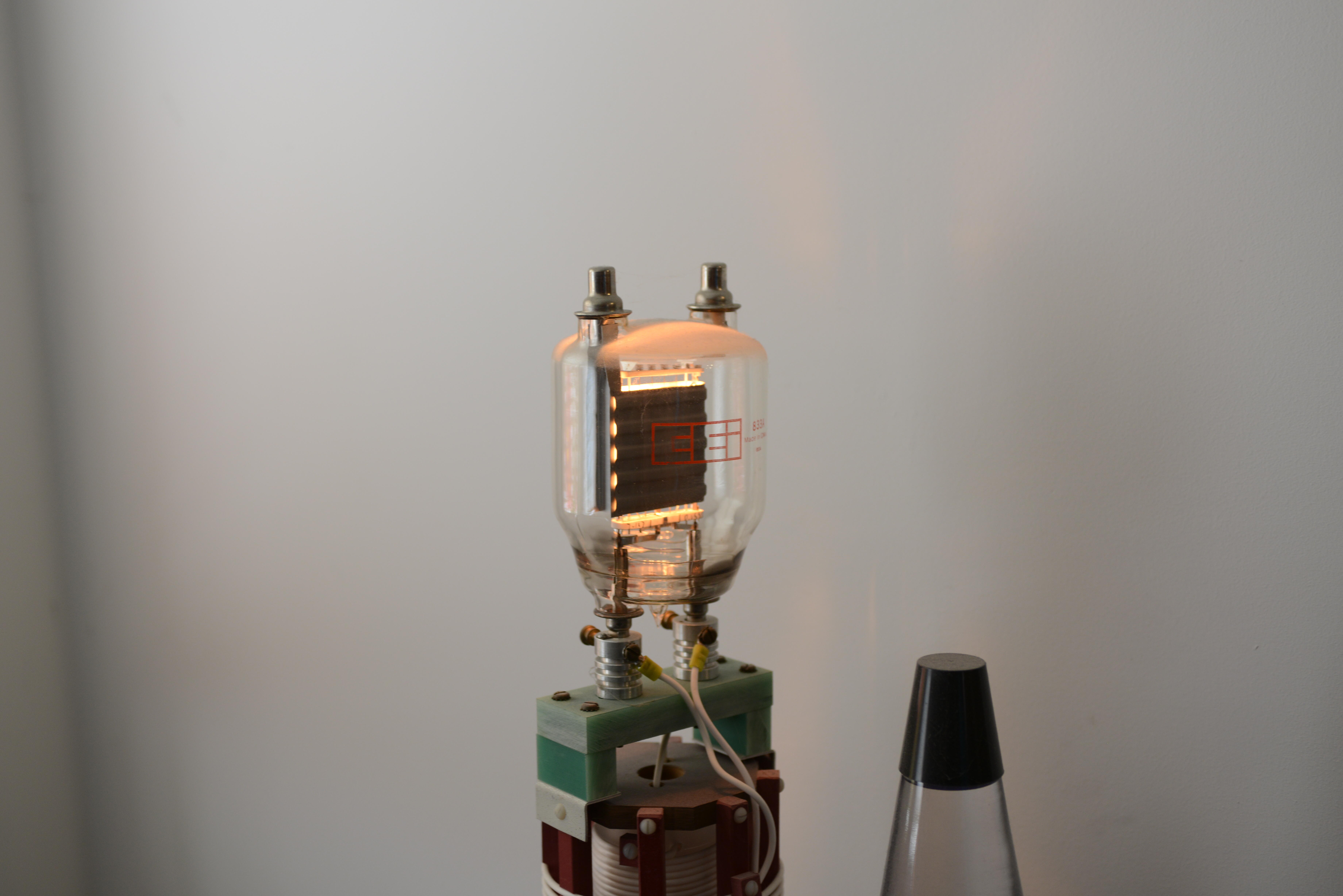
So this started a few weeks ago when someone found a picture of my 100 watt night light. Its an 833A tube. (new picture below) And he wanted a megatron made from 8 of these. (10 vac at 10 amps each tube) so 800 watts filament power just for the output tubes. By the time you make the +/- 1kv power supplies running at 40ma, and the power for the 300b driver tubes etc, way past the limit for usa 120v 20 amp service which is 1850 watts. And with the top of the tube at silly and dangerous high voltage... bad idea. So i started looking for slightly less silly alternatives. I think the 211 tube fits the bill. running with +/-750v power supplies at 35ma. So a megatron with 211 output tubes, 300b drivers and a high gain input tube. unless someone has a better idea.
-
depends on what kind of power supply is inside. if its a switcher, it might benefit the input caps for a 30 second slow ramp. if its a linear supply, probably does not matter.
-
Hey Head-Case, what's your bandwidth like?
kevin gilmore replied to Knuckledragger's topic in Off Topic
my orbi is getting glitchy too. replacement is $1500. likes to drop the dns once a week. i'm getting 1194 download and 24 upload. if i get the newest orbi, i can get up to about 1600 download with top xfinity tier. i don't need that yet, and then i would have to upgrade every switch in the house to 2gb or faster, and those are expensive too. also looks like i'm going to get a atsc 3.0 tuner very soon. there is a chicago station now that is broadcasting 4k cartoons. 3 stooges in 4k is da bomb. -
goldenreference low voltage power supply
kevin gilmore replied to kevin gilmore's topic in Do It Yourself
i don't remember. definitely can add 1 wire and not use it in shunt mode.