kevin gilmore
High Rollers
-
Joined
-
Last visited
Everything posted by kevin gilmore
-
because 4 x small transistors in parallel are faster than 1 bigger transistor. paralleling lots of transistors is still a thing on all current krell amps. if you change out the opamp to opa541 then you can boost the rails to 30v.
-
that one is identical sized.
-
bad power switch? which would be an easy fix. could also be a burned out light bulb and the amp actually works fine. or no power to the amp. voltmeter even super cheap piece of crap is very helpful.
-
that is the input fuse and looks ok. The other fuses are on the circuit boards the power light is hooked to the fuse on the right channel circuit board. That piece of paper is protecting something from shorting out and definitely was not stock issue. attached manual shows how to get the circuit board out. 2 screws and 11 connectors... pioneer_m22.pdf
-
i have the schematics if you need them. no power on light means that either of 2 of the 5 fuses have popped. If its the primary fuse, put in a new one. If its the secondary fuse, likely you have shorted output transistors. And getting parts for something that old in this covid economy is next to impossible. replacement semiconductors work but don't sound anything like the originals. And some oscillate etc... Or just replace all 5 fuses and turn it on and see what happens. You might get lucky But given its age... input fuse is 3 amp amplifier fuses, 2 each on each circuit board are 500ma all are 3ag size
-
no power on light? There are 5 fuses inside. You will need an ohmmeter to actually check them.
-
the janzen caps are definitely between stage 2 and stage 3. The orange caps are the output caps. the output is a center tapped inductor, not a transformer. B+ is 525 volts on the center of the transformer.
-
even the mistakes are outrageous.
-
Best place to measure is the scope set to AC and tied to either side of the janzen caps. the side next to the gain tubes is likely to be about +150v dc with music riding on it, probably 15 volts of peak to peak AC when volume is cranked. There should be music on both sides of both janzen caps. If there is still music on the caps when the sound disapears then the problem is the output tubes or output transformer
-
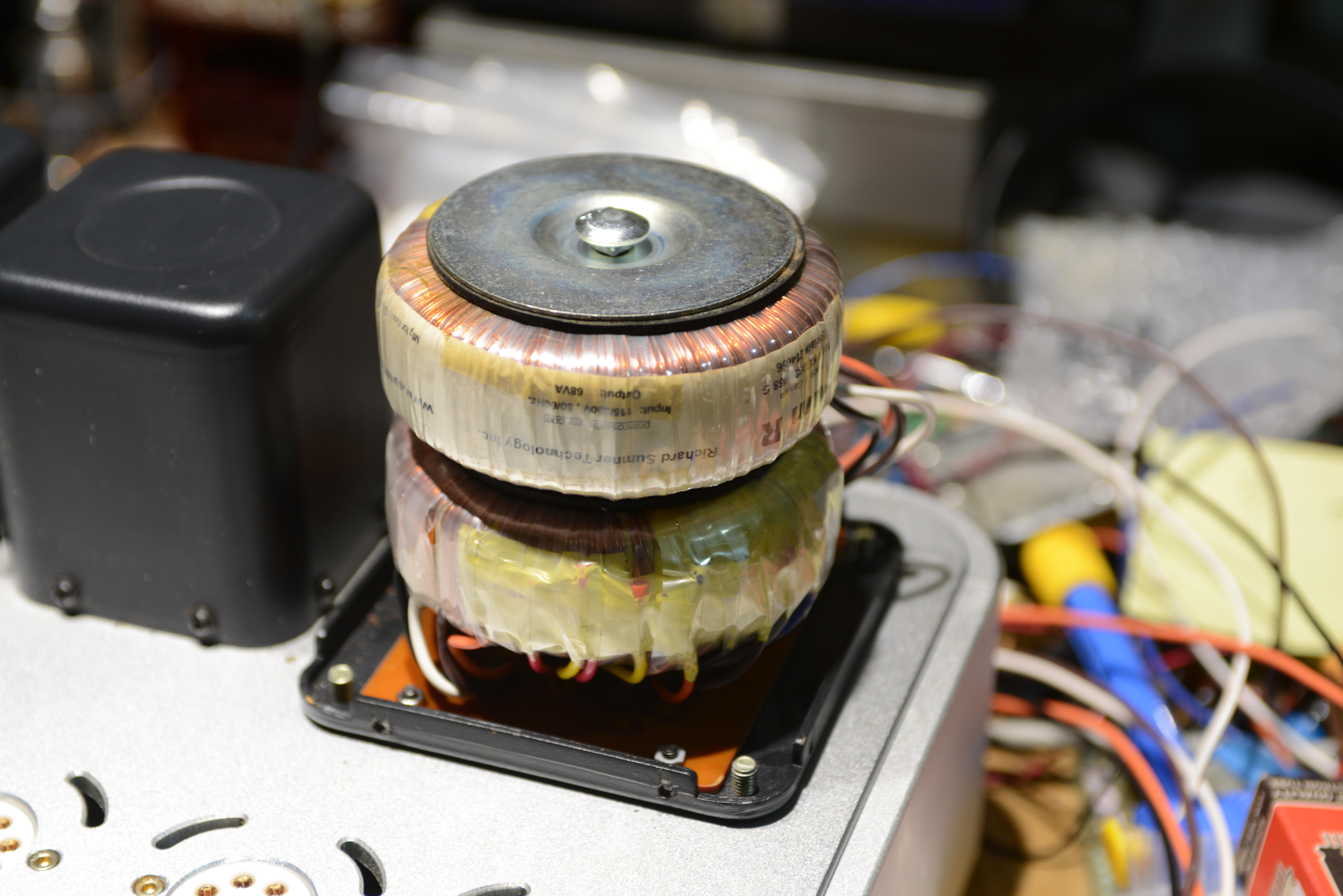
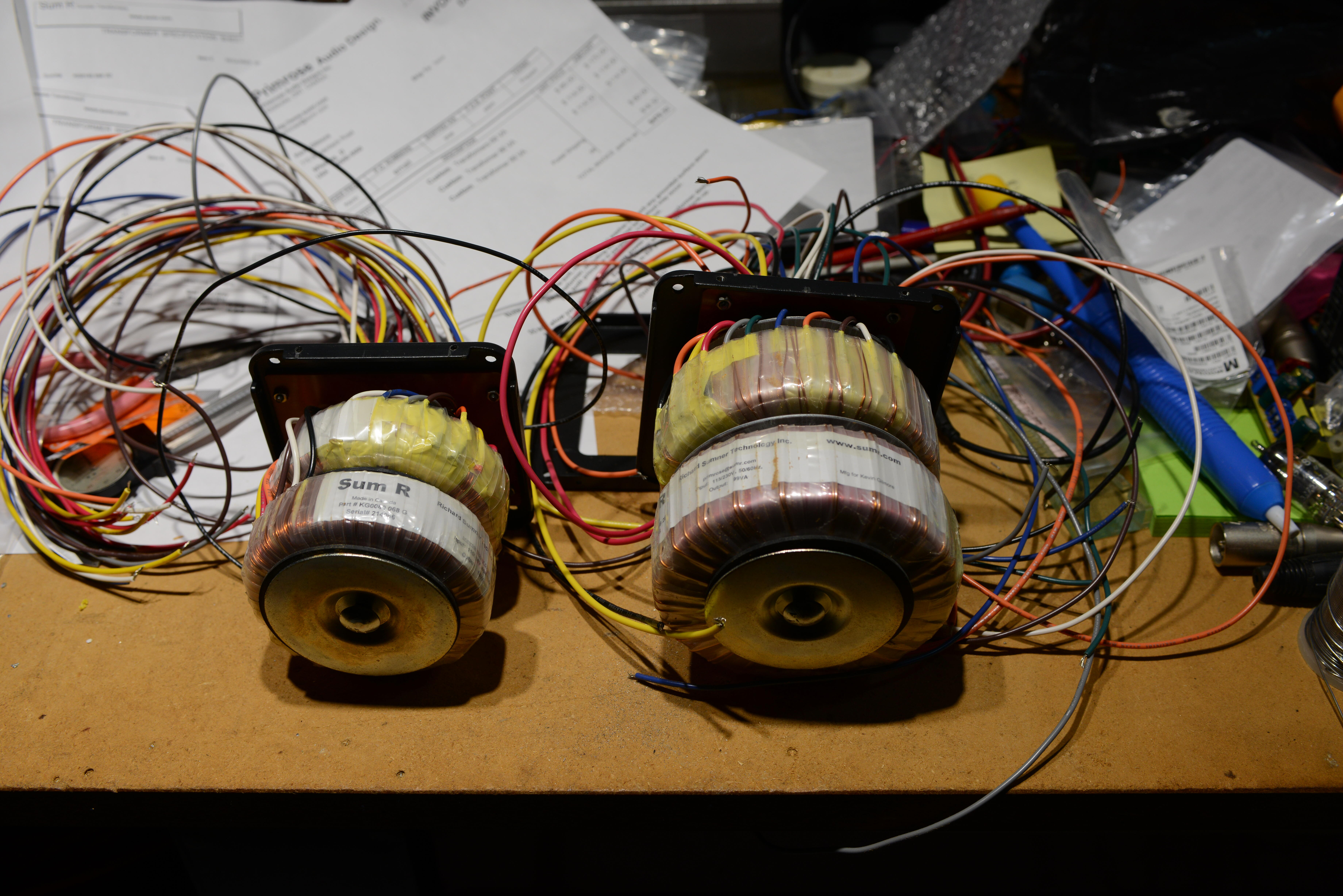
Tore one of the dead transformers apart. At least a little bit. There was no wiring error. 3 amp winding is .0485 inch diameter which is 17 gauge and good for 2.9 amps (2 x el34) 1.5 amp winding is .0295 inch diameter which is 21 gauge and good for 1.2 amps (1 x el34) American Wire Gauge Chart and AWG Electrical Current Load Limits table with ampacities, wire sizes, skin depth frequencies and wire breaking strength (powerstream.com) Other charts do less current. Some charts do higher current. So at a minimum, right on the absolute edge. Can’t get deep enough to measure the primary winding which might be more important. and the bergquist stuff is non-stock, lead time 26 weeks Some of the toroid companies sell covers for their transformers. I would think that as a blackbody radiator, they would help the cooling, not hurt it. But next time i will be testing without the covers on. With the transformers the amp is tipping the scales at 75 lbs. Making it really hard to work on.
-
compared to the wire sizes on the T2 transformer, these new transformers have wire sizes at least 1 size smaller on all the secondary windings. if i had another t2 transformer which i don't i would put both in the can and test for that. on the high voltage transformers which i have not lit up yet, the 5v windings are definitely 2 wire sizes too small. i don't want to pick on richard because everything else in the past was perfect, but these transformers lasted less than 1 hour. i did finally get a quote from tigertoroids.uk and they say they can definitely do it, and have seen all the pictures. with a outside diameter of 95mm and 49mm high. virtually identical in size to the sumr transformer.
-
nope, bolt not touching either the top or bottom. bottom is circuit board fr4 material.
-
did not know to measure the current before they blew up. richard has all the pictures.
-
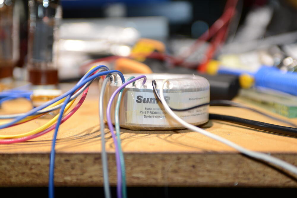
i guess i don't understand. This is the sumr transformer from 13 years ago from a T2. Virtually identical size in every way to the transformers above. After 2 hours, 5 degrees above ambient.


-
a scope is a good thing to have. plenty of high voltage probes on ebay. like this Oscilloscope Scope Test Probe P4100 100:1 High Voltage Withstand 2KV 100MHz 1.2M | eBay
-
know anyone you can borrow a oscilliscope from. (with high voltage 100x probe) ?
-
anyone know how to hand wind toroid transformers? where to buy wires, cores etc. better yet, r-core transformers and bobbins.
-
i'm assuming that all the meter numbers don't change when the channel cuts out? which kind of eliminates the front end tubes and circuitry?
-
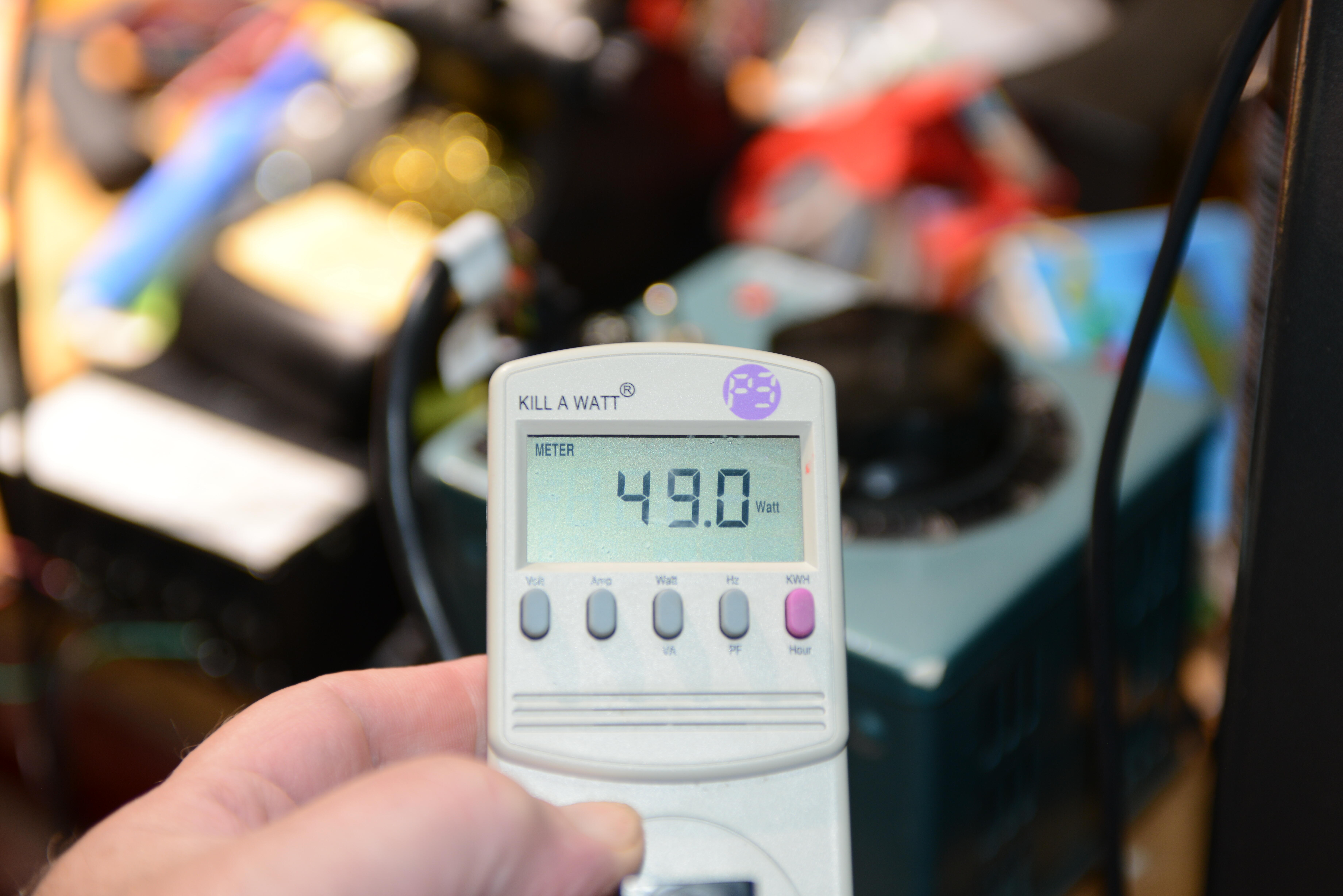
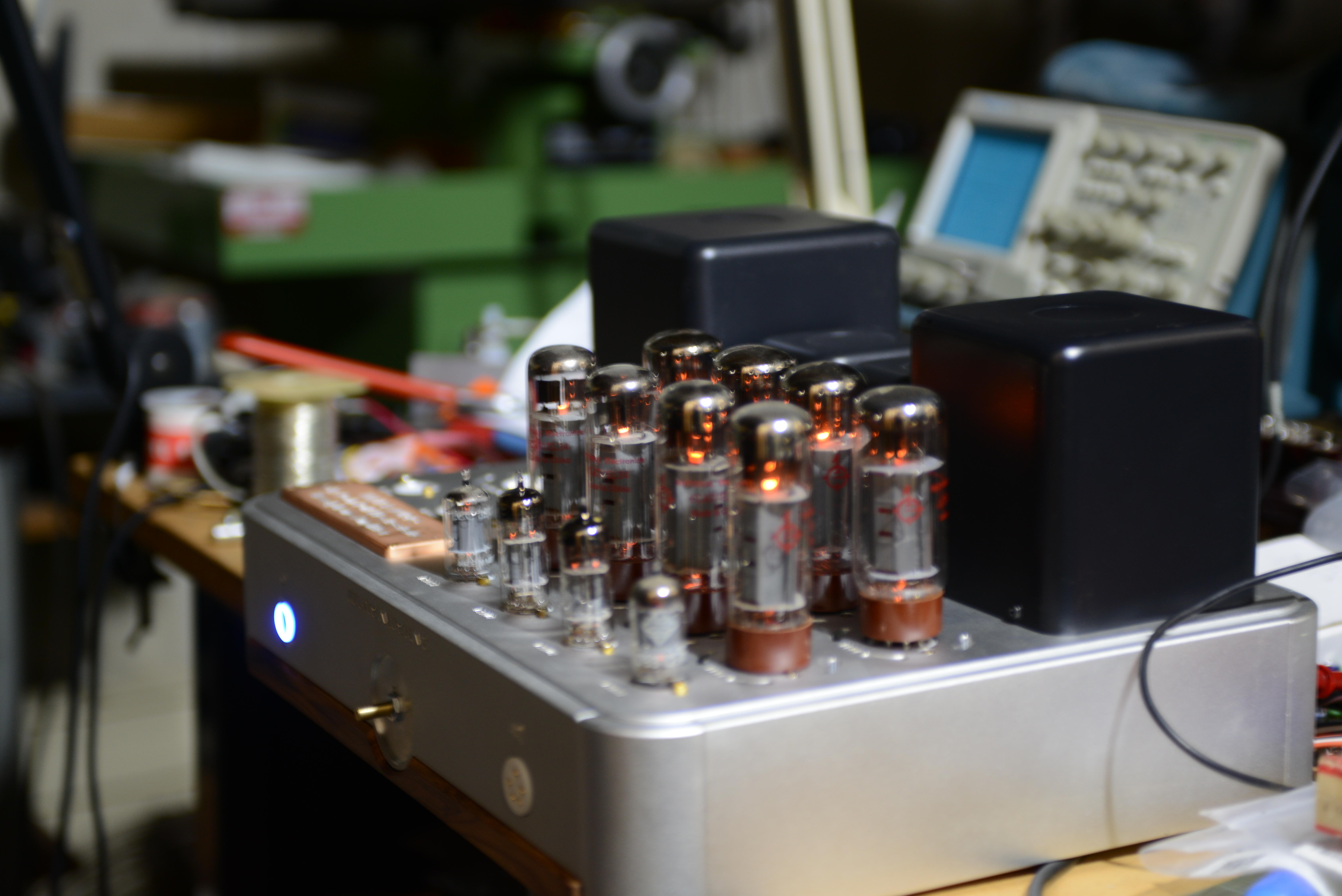
both transformers now have shorted primaries. And the smell of burned toast. This is just driving the filaments and every output tube was getting about 6.2 volts. (and input tubes were getting 12.5 volts) transformers are 68va and say so. each drives 4 x 6ca7/el34 plus a 12au7 and 12ax7 4 x 6.3 x 1.5 = 37.8 watts 2 x 12.6 *..15 = 3.78 watts so a total of 40 watts should have worked.

-
good news, BAD news as far as i know, this is not safe.


-
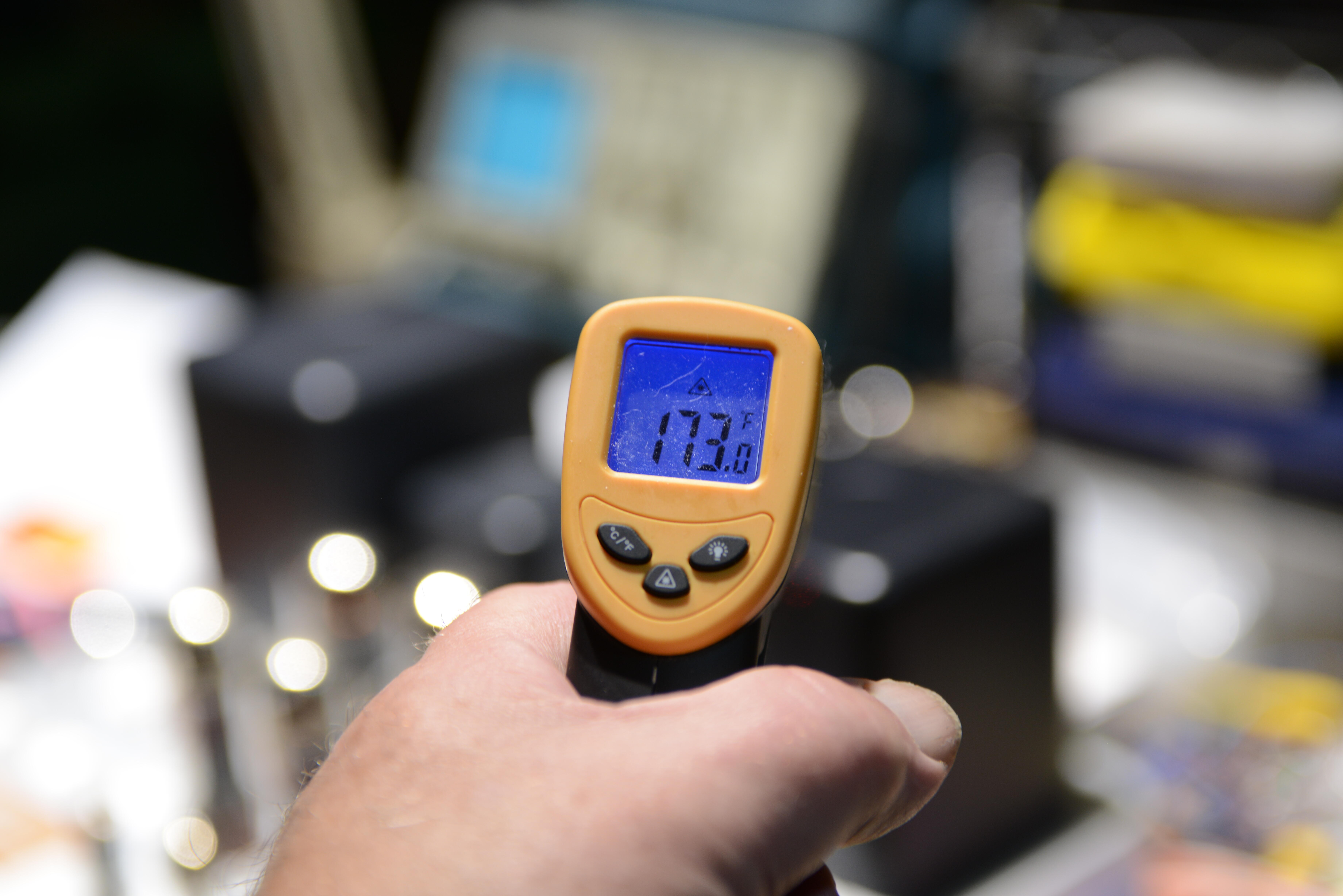
it is possible that parts of the power supply are dual mono and one side is getting too hot for some reason, or one of the electrolytics is causing trouble. Get an infrared thermometer and see if anything is getting hot.
-
in the past, craig had trouble with all those white plastic connectors with poor crimp on the pins. look carefully for browning or burning on these connectors, removing them one at a time and reseating them.
-
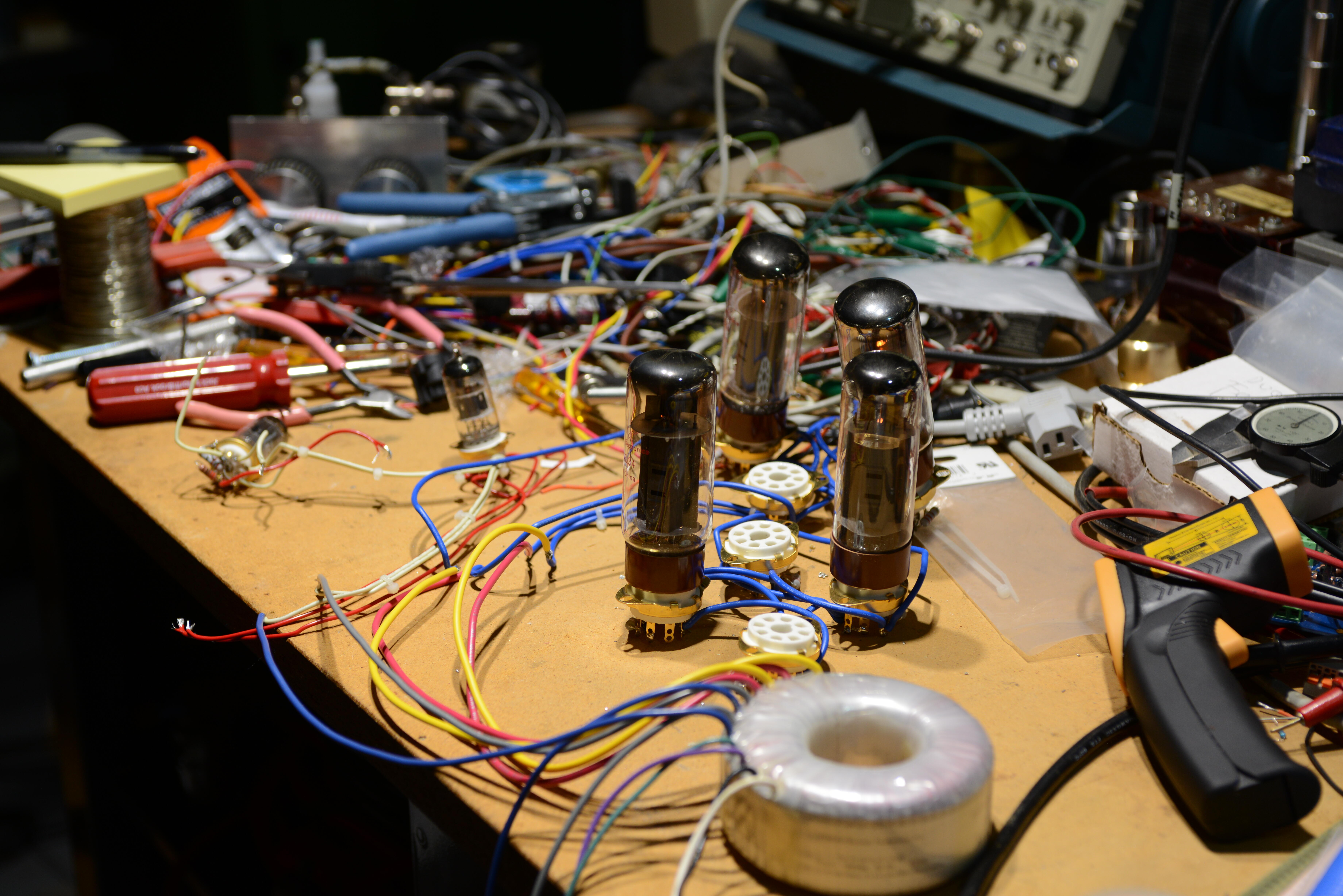
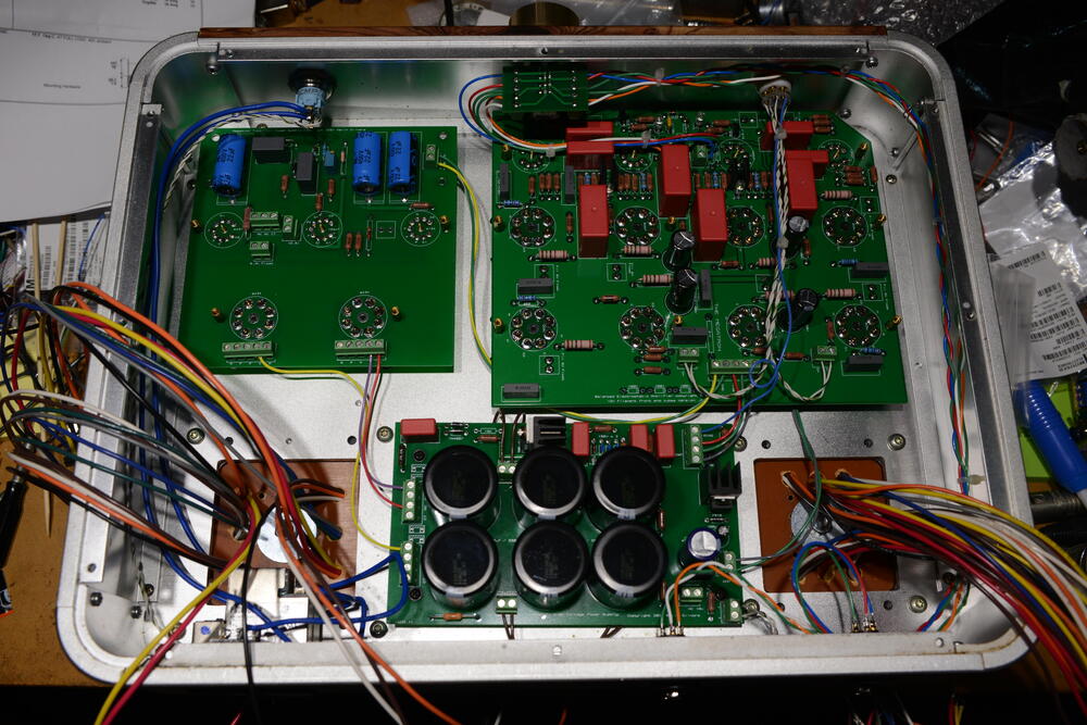
so many wires

-
bc546/bc556 starting to get very hard to get even though onsemi says they are going to make more, so this which needs massive amounts of checking.
-
new document link https://drive.google.com/drive/folders/152thxfZafBmisG0CKCv6X82V-Ch9TjMH?usp=sharing