kevin gilmore
-
Posts
7,114 -
Joined
-
Last visited
-
Days Won
21
Content Type
Profiles
Forums
Events
Everything posted by kevin gilmore
-

Megatron Electrostatic Headphone Amplifier
kevin gilmore replied to kevin gilmore's topic in Do It Yourself
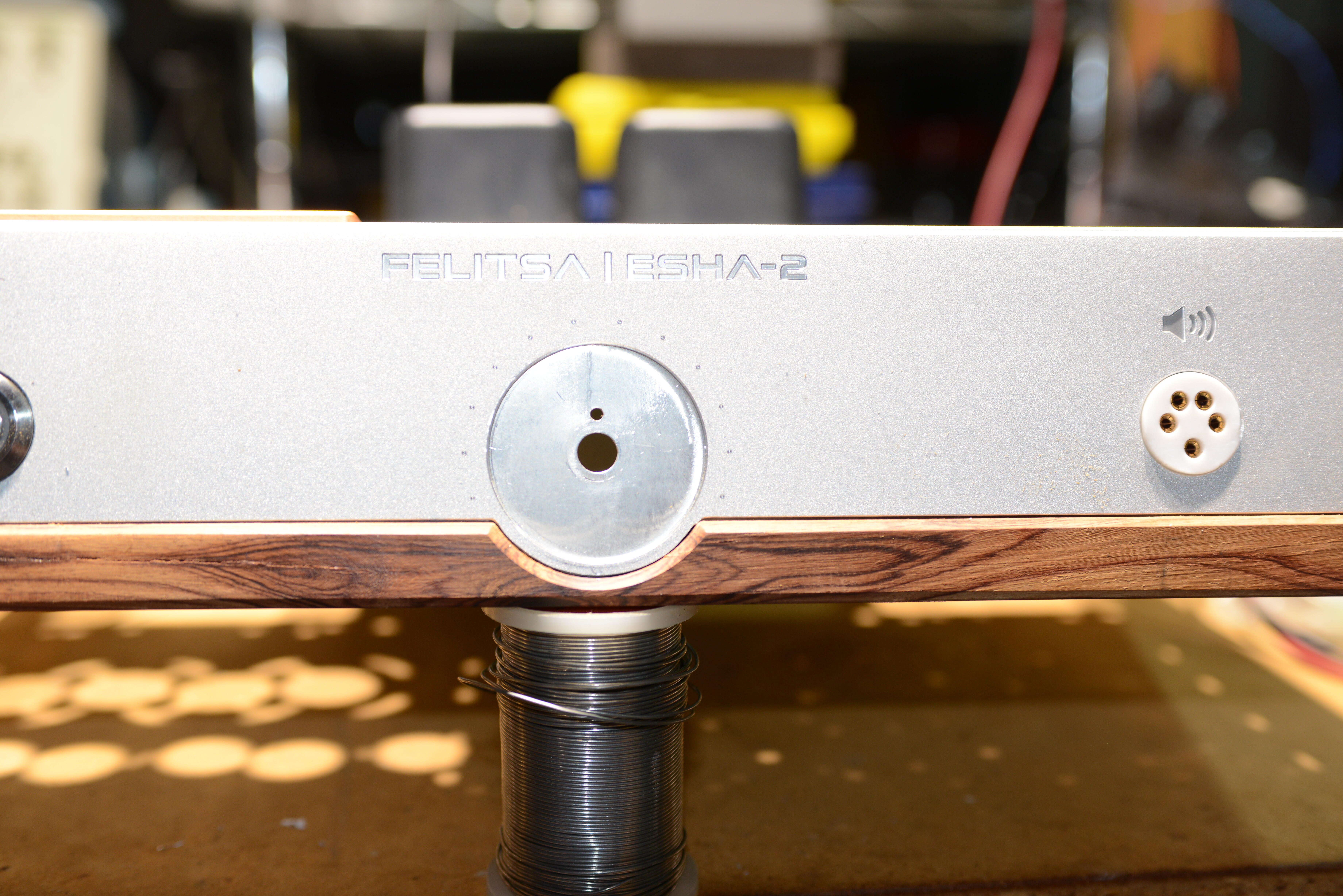
So more than 30 minutes to disassemble the front panel, 10 minutes to get it aligned into my emco fb5, and 10 seconds to put in a fucking hole that should have been there from the start. Notice the fucked up stax jack and the shitty finishing on the wood.
-
Megatron Electrostatic Headphone Amplifier
kevin gilmore replied to kevin gilmore's topic in Do It Yourself
this is a put together chassis of a specific size. where he bought the chassis i do not know, but it completely comes apart, all 4 sides, the round corner pieces etc. Then he had the front,back and top all machined. all panels are .2 inch thick. And the front wood piece is esentially a stick on made of unknown wood. absolutely every single thing about this is fucked to the max. broke the anti-spin pin off the pot and did not even bother to drill a single hole to prevent the pot from spinning. Some of the work was definitely done by an nc mill, and a really shitty one at that. on the mill i used, everything was accurate to .00001 inch, and it really was at least this accurate. this thing is barely accurate to .008 inch. nothing on either inch or metric boundaries. and the holes for the power supply board were drilled by hand, and blind tapped, 2 of the 4 holes went all the way thru the panel. But the worst is the way under-rated power transformers which were potted with definitely the wrong stuff. And wiring all the filaments together. And the stax jack it turns out is also massively fucked. And force held in with rubber o-rings. Gold plated hex screws with the gold coming off. And the tube sockets were really low quality garbage, as bad as the russian crap that mikhail used. The 3 boards from jlcpcb were a total of $65 with shipping. and shipping was half the price. The hand dremel tooled boards were so utterly fucked, no reason for any of this. Somebody really high on really bad drugs did this. Not even mikhail or mike bean (hennyo) could do something so utterly and completely fucked. Wow, i gave hennyo a compliment, yikes. The 300v tube supply is actually pretty clever and kind of unique, but also utterly fucked because he had the pass tube cathode wired to ground when it had to be connected to 300v. And the bias supply with a 100k series resistor. Guaranteed to kill your headphones. Its not my money going into this, so i will continue till its either completely finished and working or the tube diode power supply cannot be made to work. Looks like the repair price will be about $1500 in parts, plus the original purchase price of about $5k. All the improvements to the amp board are in the new board. There are places for solid state diodes on the power supply just in case. There is no reason for any of this. So far i have about 30 hours of labor in this. The mikhail es1 ended up about 50 hours of labor. Yes i'm fucking nuts. all you have to do is take my board files, have them made, stuff with parts, slap into chassis. how fucking hard can it be. -
my board does not have the delay cap. really does not need it since its going to wait for all the voltages to be within range to connect the relay.
-
Megatron Electrostatic Headphone Amplifier
kevin gilmore replied to kevin gilmore's topic in Do It Yourself
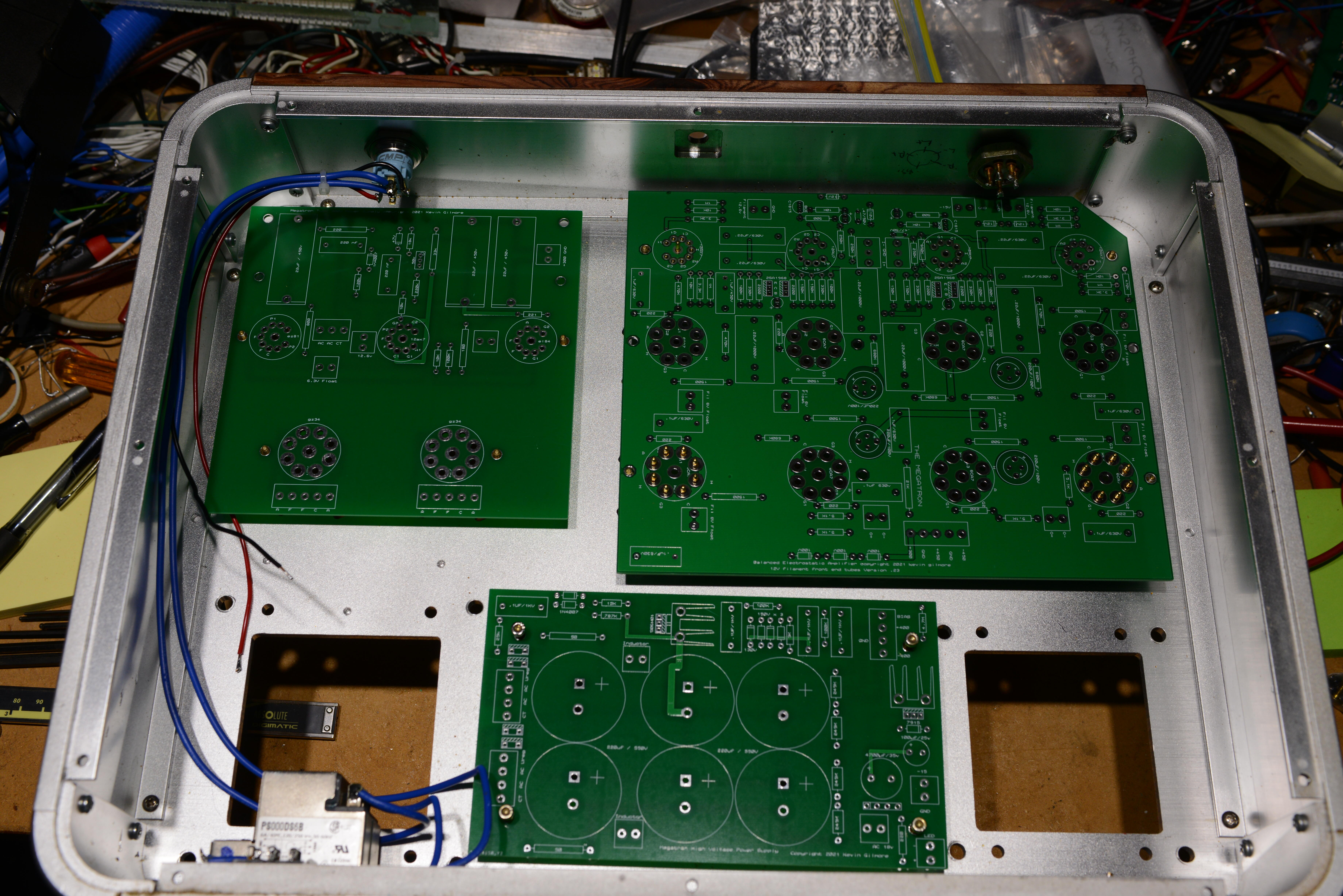
boards actually fit. well shit.
-
https://drive.google.com/drive/folders/1r3g2TAtBUaBdiMorTWX7yYgeJ7maQbYW?usp=sharing
-
https://drive.google.com/drive/folders/0B7egryukiT7_TFlEQlBRejdVdDQ?resourcekey=0-nGWwBYQ_Uivj-ciBLYMeaA&usp=sharing
-
you probably want to find and use my protection circuit. less parts. and also does balanced if needed
-
Megatron Electrostatic Headphone Amplifier
kevin gilmore replied to kevin gilmore's topic in Do It Yourself
gz34 -
Megatron Electrostatic Headphone Amplifier
kevin gilmore replied to kevin gilmore's topic in Do It Yourself
boards and transformers ordered. -
i think i fixed it, someone test please.
-
Megatron Electrostatic Headphone Amplifier
kevin gilmore replied to kevin gilmore's topic in Do It Yourself
yep that sounds about right. The resistance of the inductor is 100 ohms. -
Megatron Electrostatic Headphone Amplifier
kevin gilmore replied to kevin gilmore's topic in Do It Yourself
636v center tapped transformer dual tube diode, 220uf to ground 5H inductor 2 x 220uf to ground. The turn on thump puts about 700v on the first cap. which is why the caps blow up. adding 50 ohms after the diodes softens the bump. whats the best way to calculate the required primary voltage for 400v at 100ma dc output. -
do no replace these parts. buy from someone that has them or wait.
-
Megatron Electrostatic Headphone Amplifier
kevin gilmore replied to kevin gilmore's topic in Do It Yourself
So this is what its going to look like when its done. And Hammond is willing to do the custom transformers. With a price that matches the complexity. Anyone with experience with tube rectifier power supplies driving 5 Henry inductors?
-
Megatron Electrostatic Headphone Amplifier
kevin gilmore replied to kevin gilmore's topic in Do It Yourself
hey joamat wanna make a couple of test boards before real money is spent?
-
Megatron Electrostatic Headphone Amplifier
kevin gilmore replied to kevin gilmore's topic in Do It Yourself
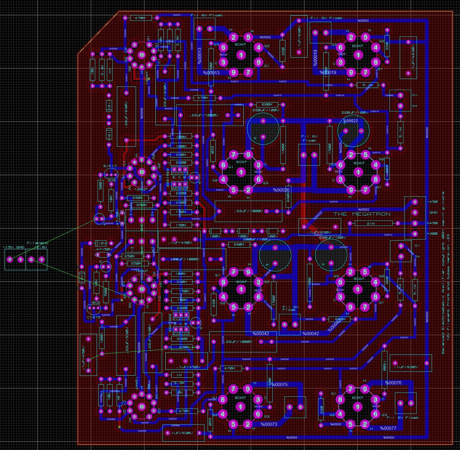
joamats hand made boards look much better than that. posted latest schematic. Does anyone recognize the tube power supply? And the output tube has 300v cathode to filament on a tube rated at 100v. Does (did) it even work? birgir mentioned this earlier. have a look Image-Hifi.com-62015-Viva-Audio-Solista.pdf (audiograffiti.com) so lots of very high voltages, lots of heat and flammable felt and a horrible point to point job. But wait, there is more, my good friend ray samuels and his A10. 5687 output tubes in srpp configuration running with a plate voltage of 500v. So at peak output voltages the cathode of the top tube sees 500 volts with respect to the cathode on a tube rated at 100v. How does this even work? megatronschem2.PDF -
Megatron Electrostatic Headphone Amplifier
kevin gilmore replied to kevin gilmore's topic in Do It Yourself
the biggest problem is that the tube sockets are up to .02 inch off in both x and y. really hard to make a circuit board with tube sockets fit into the holes with a top panel that is .35 inch thick. and all the blind holes for the other board mountings were hand tapped and then the holes in the boards were made bigger till it fit. this is so hopelessly fucked. might have to make the holes in the tube sockets much bigger to allow for the slop. No room for a regulated power supply. do want to know how the dremel tool work was done. also corrosion all over the place when the electrolytics let loose. at least we finally have an example that is much worse than the singlepower es2. not sure how to continue. -
Megatron Electrostatic Headphone Amplifier
kevin gilmore replied to kevin gilmore's topic in Do It Yourself
the input wiring is monster cable magnetically shielded cable. Says so right on the cable. And it was a quad balanced pot wired as unbalanced. -
Megatron Electrostatic Headphone Amplifier
kevin gilmore replied to kevin gilmore's topic in Do It Yourself
bias circuit DO NOT DO THIS!!! megatronschem2.PDF -
Megatron Electrostatic Headphone Amplifier
kevin gilmore replied to kevin gilmore's topic in Do It Yourself
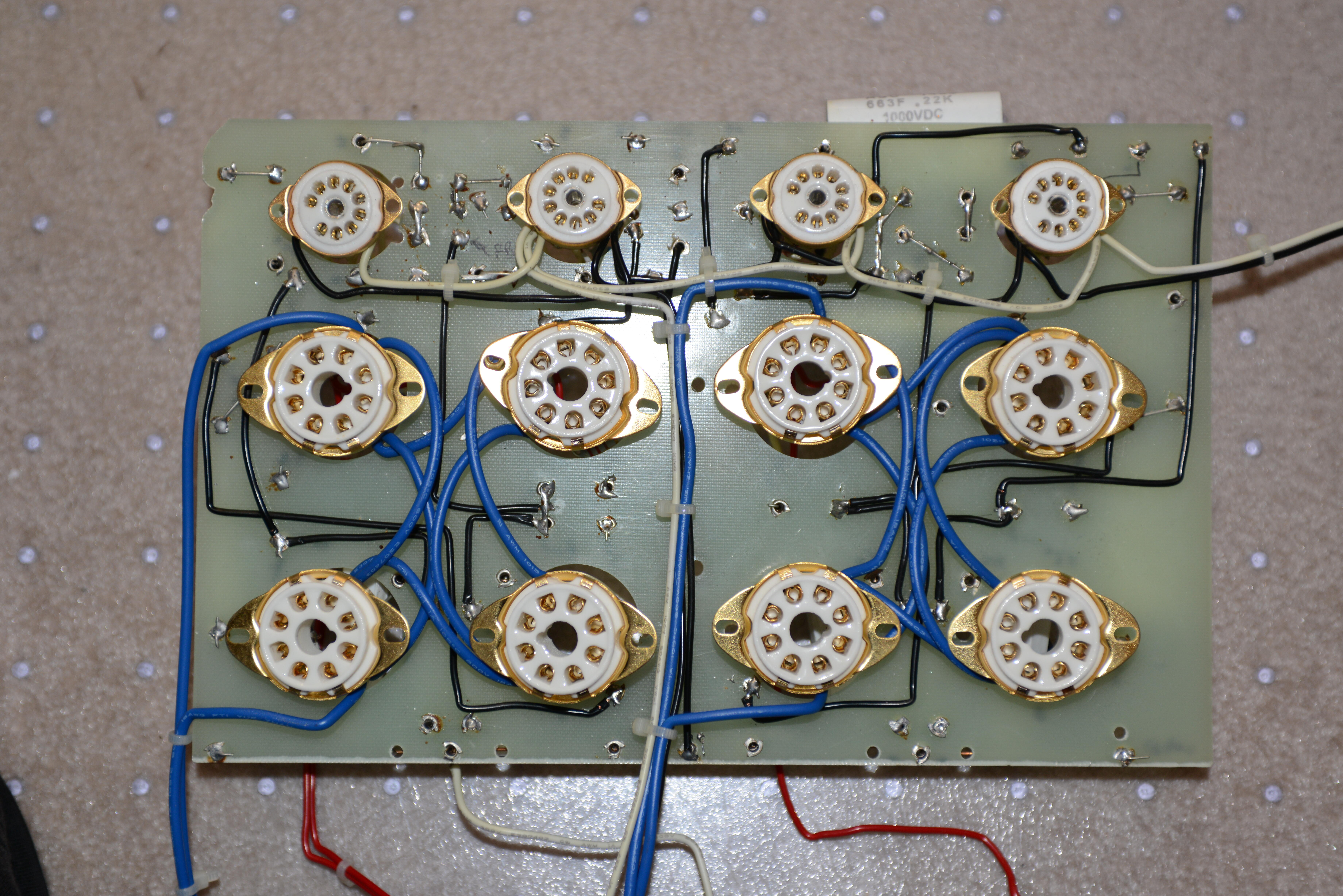
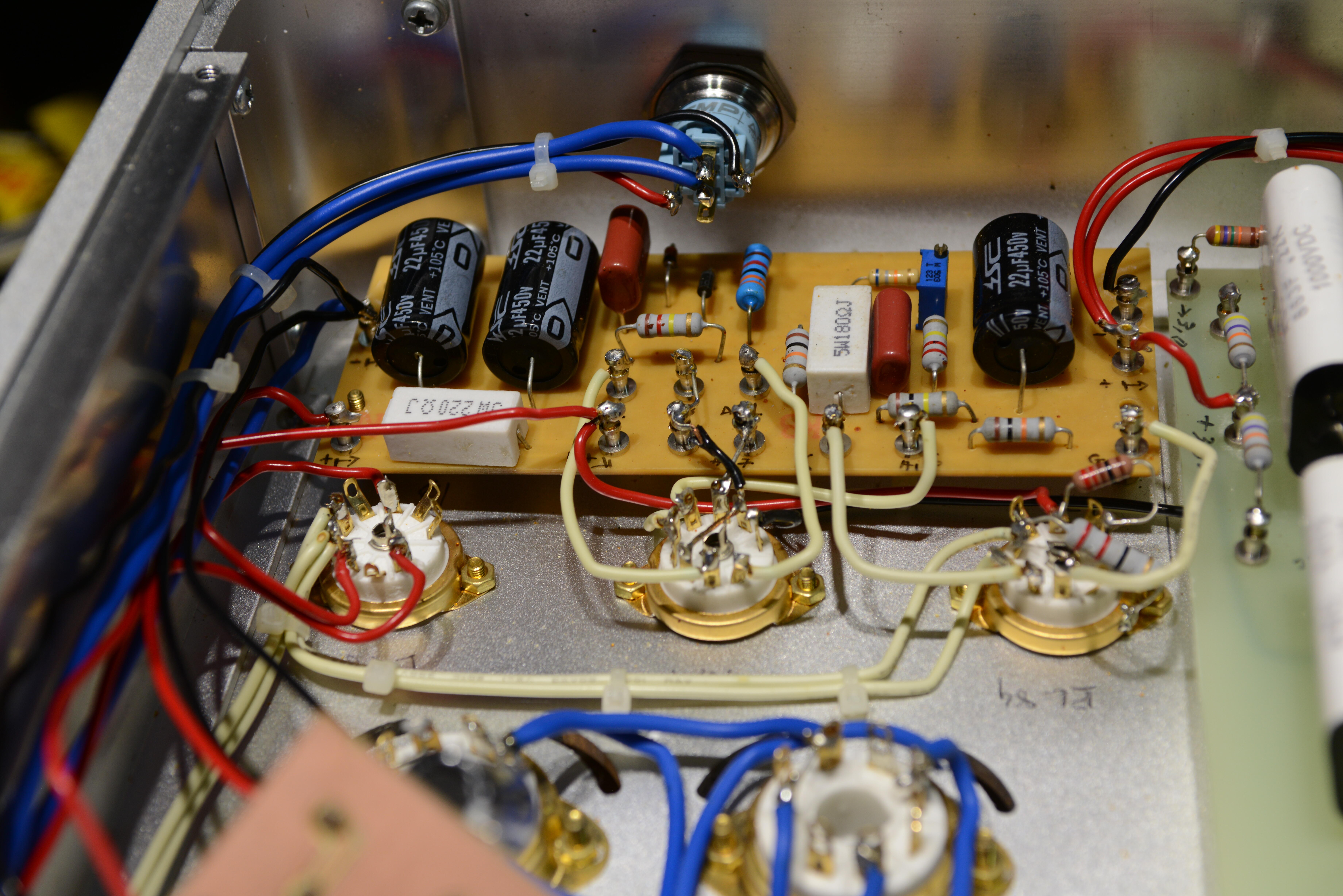
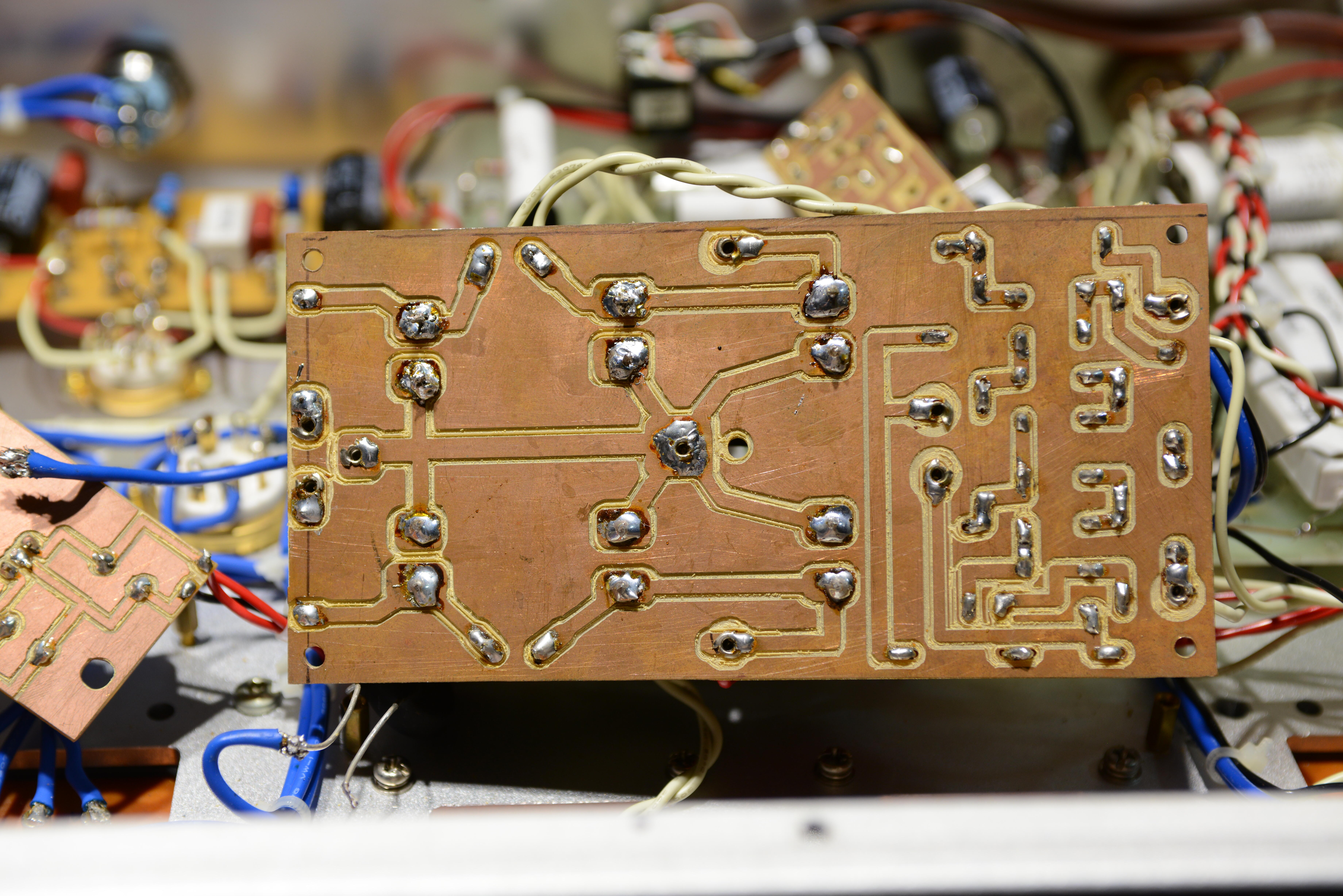
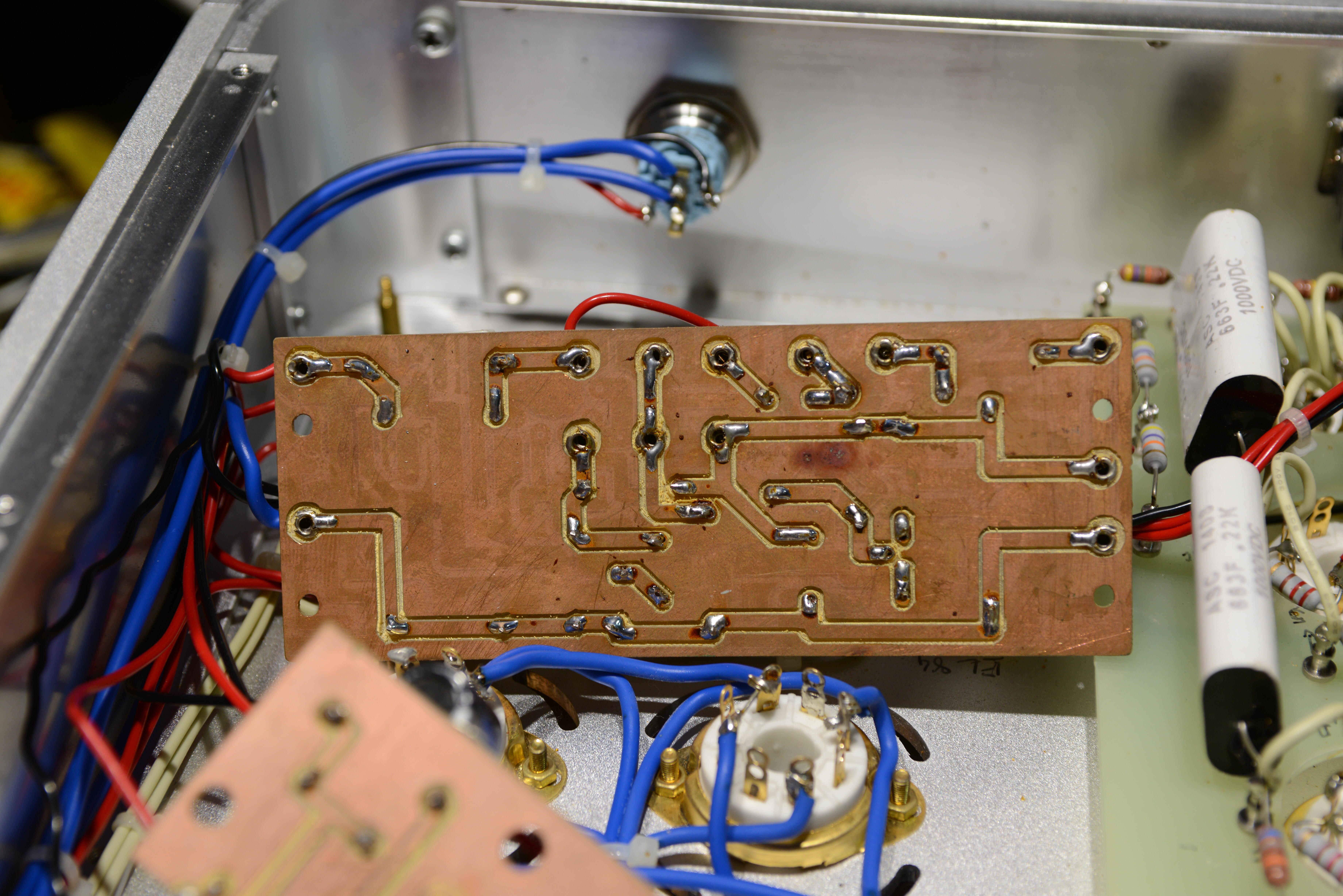
back of circuit board. look at that filament wiring. and the corners notched out of the board. bias board. its even worse, after the 100k resistor 2 x .022uf caps to ground tied directly to the headphones.
-
Megatron Electrostatic Headphone Amplifier
kevin gilmore replied to kevin gilmore's topic in Do It Yourself
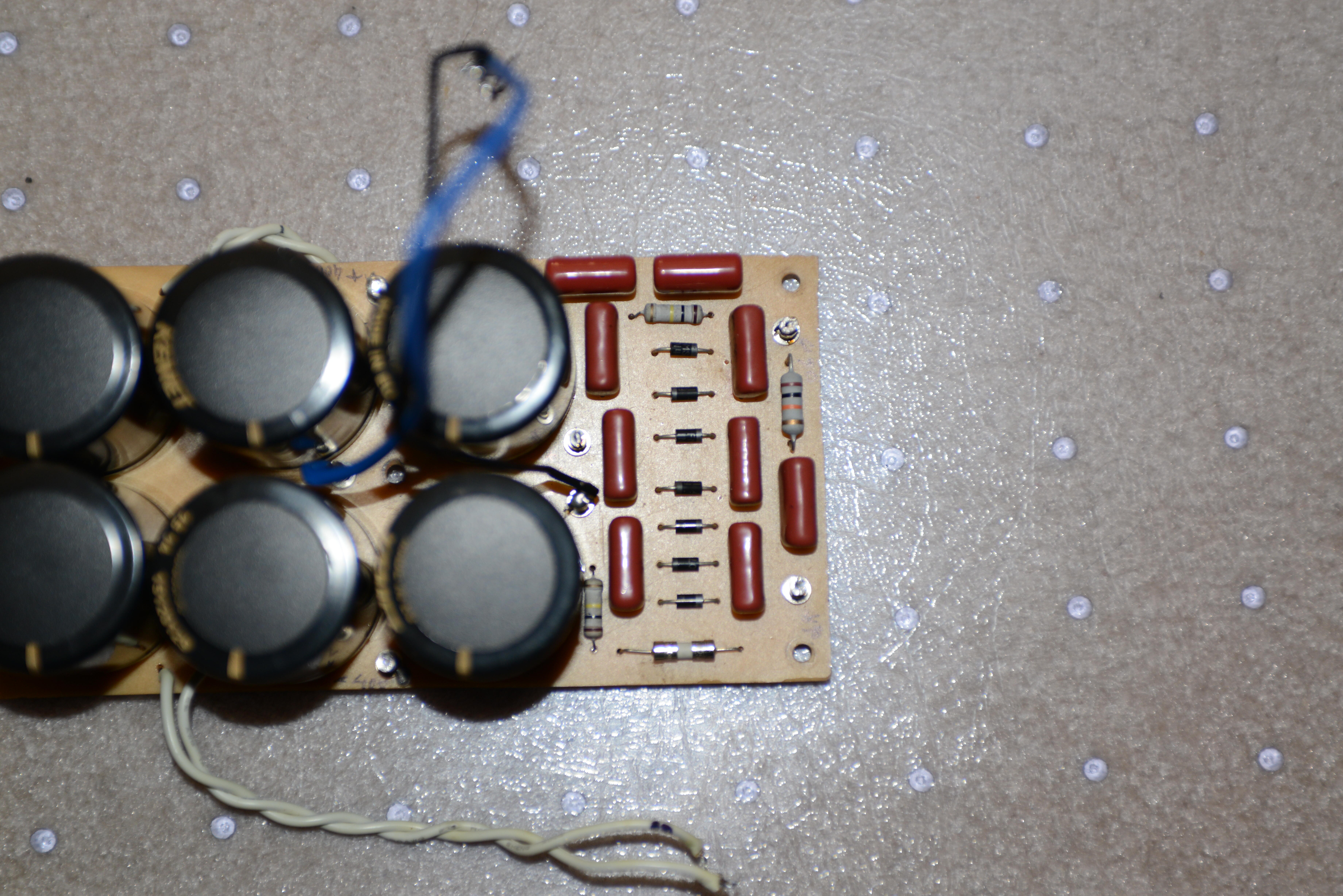
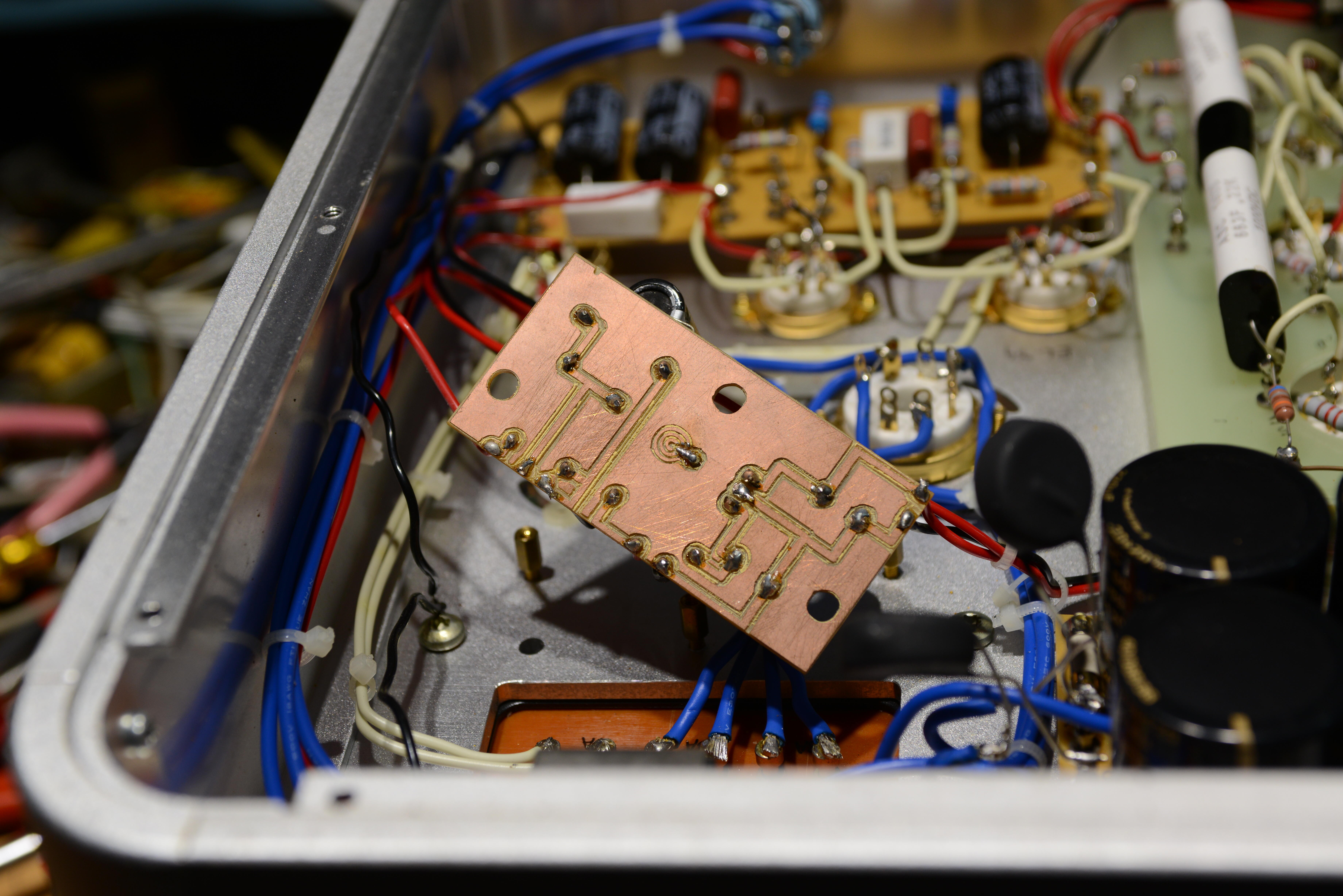
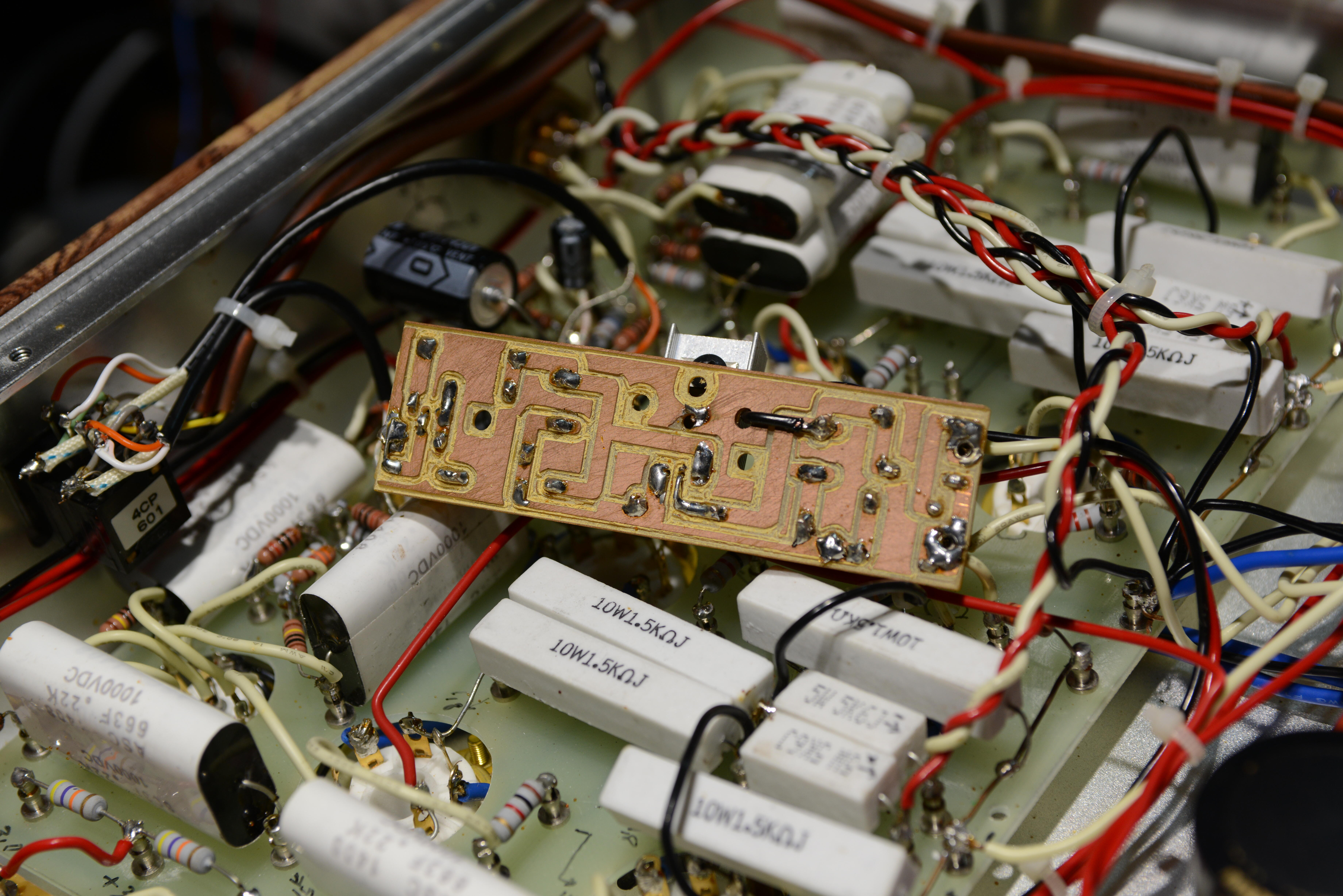
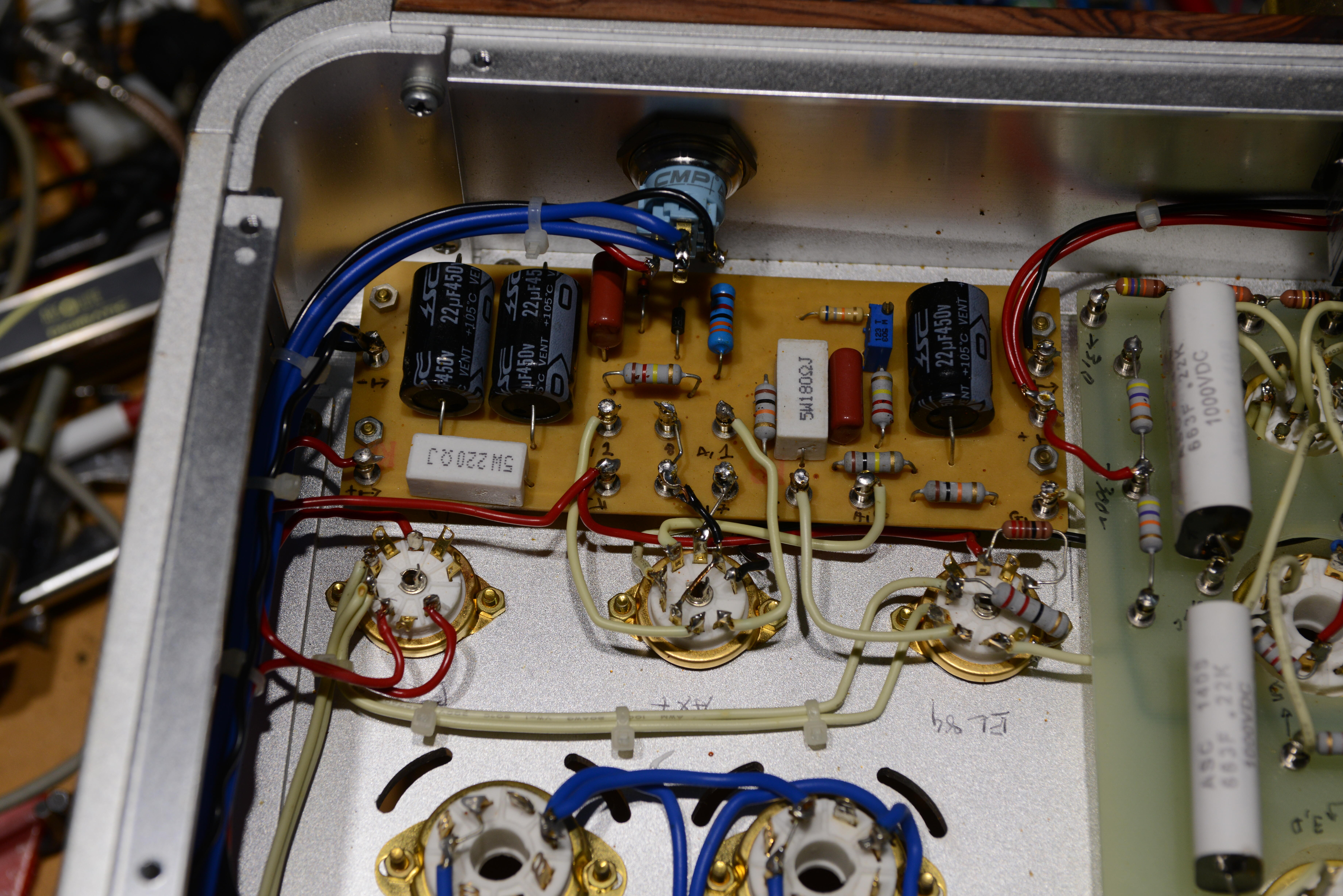
So i figured that i would test the 300v supply to see if its worth saving. But no, BOTH transformers are < 1 ohm on the primary. But no way was i expecting this. And the bias resistor for the headphones really is 100k. Very bad for the headphones. A voltage multiplier *7 from 90v. unregulated, no zeners, no protection, no anything. But wait there is more, hand made circuit boards with a dremel tool. This all has to go. But wait, the first picture is a regulated power suppy whose sole job is to drive the power led in the switch.
-
Megatron Electrostatic Headphone Amplifier
kevin gilmore replied to kevin gilmore's topic in Do It Yourself
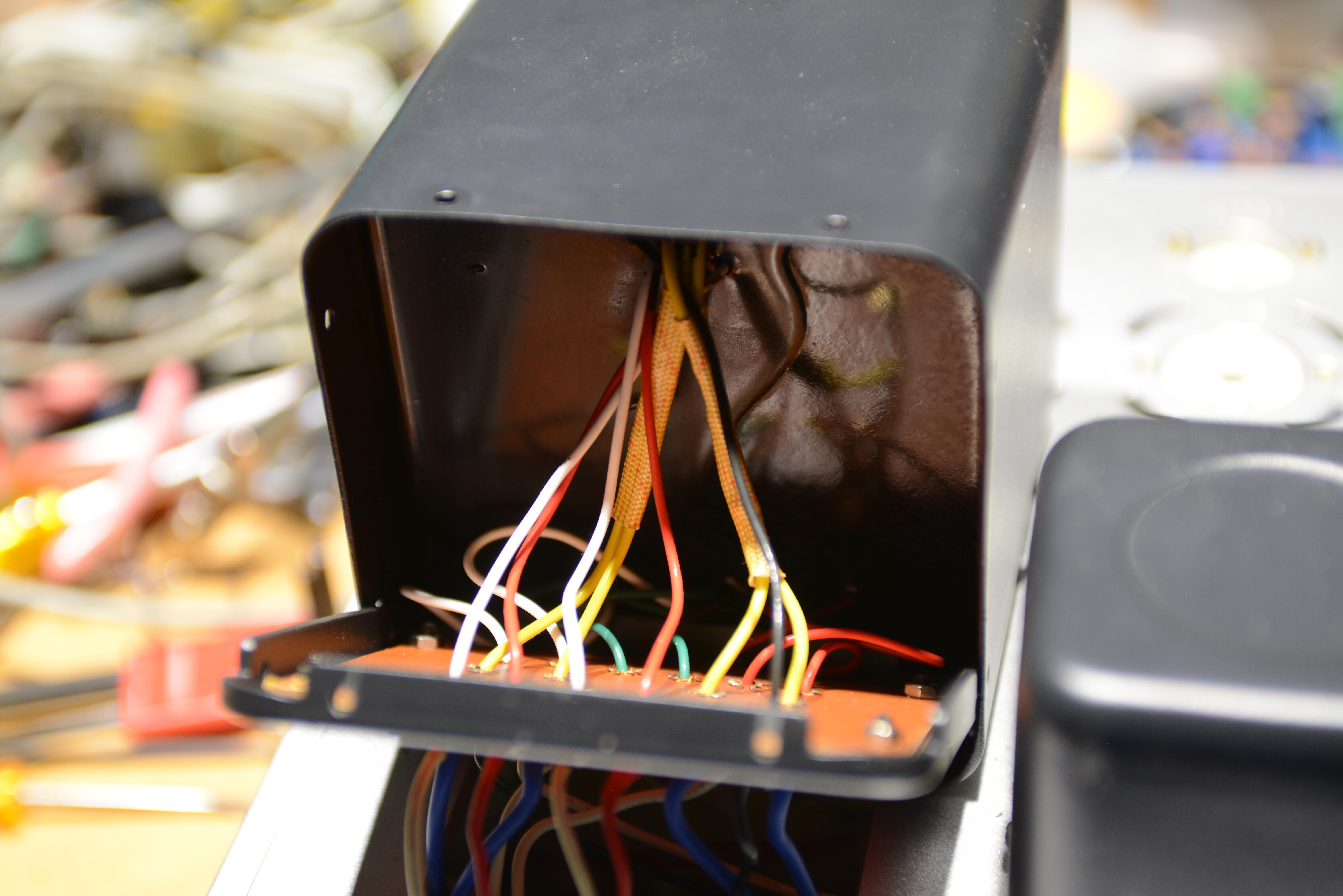
its here filament transformer for sure smoked. as in hole in the potting likely where the flames were shooting out. has that wonderful singlepower extreme smell. If anyone knows where to get transformers like this made, let me know. specs are as follows. Filament transformer, mounting holes 85mm square threaded with 4.5mm bolts 4 x 6.3 volt at 2 amp 2 x 6.3 volt at 4 amp 1 x 12.6 volt at 1 amp 18 volts @ 1 amp Primary 2 x 115vac High voltage transformer, mounting holes 100mm square threaded with 4.5mm bolts Primary 2 x 115vac 2 x 5 volt at 2 amp 2 x 630volt center tapped at 200ma 510 volt center tapped at 130ma 6.3 volt at 1 amp So many bad solder joints. grounding shields on the small tube sockets essentially force removed with a side cutter. Yikes. Notice the required missing corner out of the new board. Fucking idiot made the case first then found a way to cram everything inside.
-
https://drive.google.com/drive/folders/1r3g2TAtBUaBdiMorTWX7yYgeJ7maQbYW?usp=sharing new link, files uploading includes all new zip files published since the first upload.
-
does not work for me either. that google drive is birgirs i think lucky i have all of this backed up in many different locations
-
Megatron Electrostatic Headphone Amplifier
kevin gilmore replied to kevin gilmore's topic in Do It Yourself
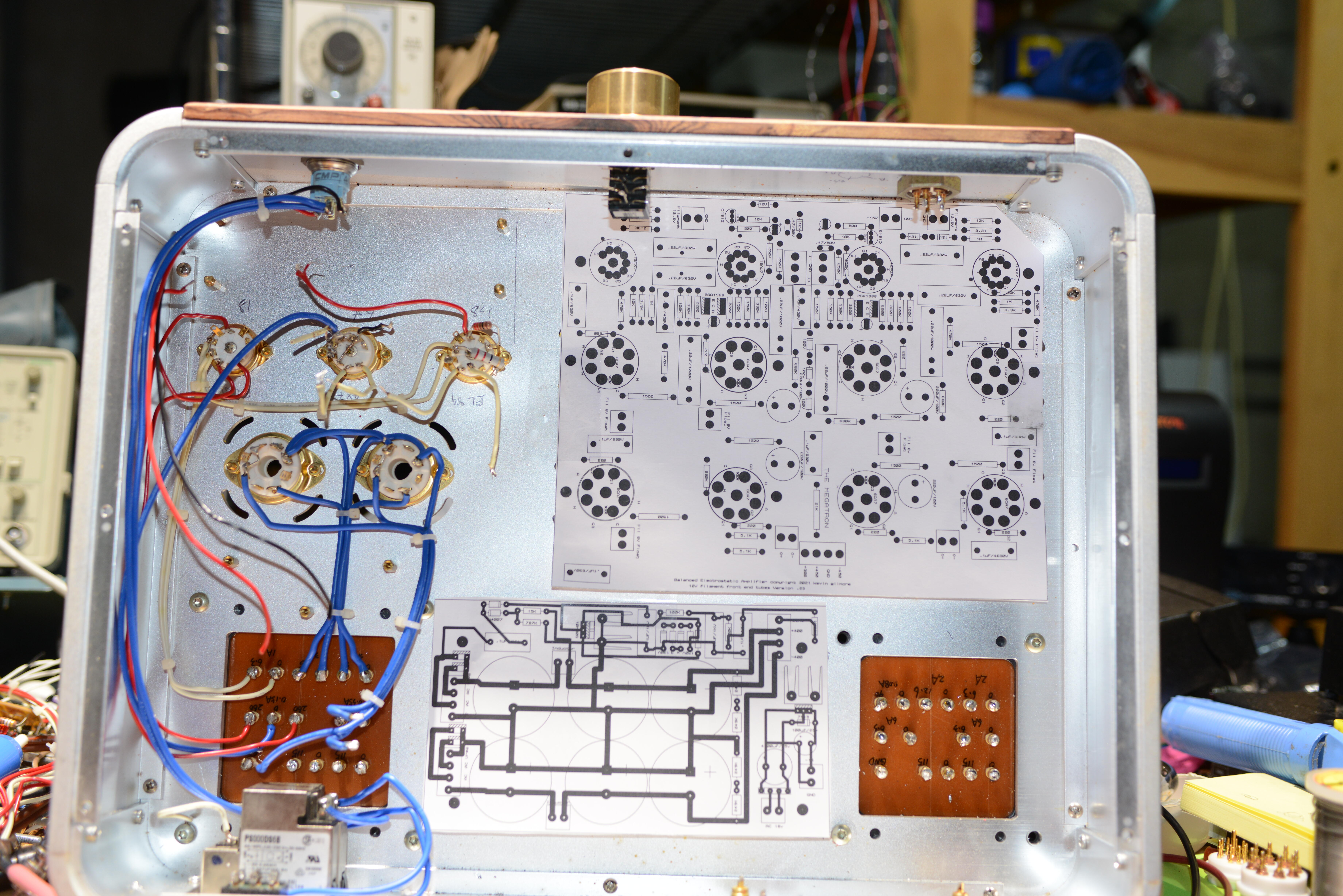
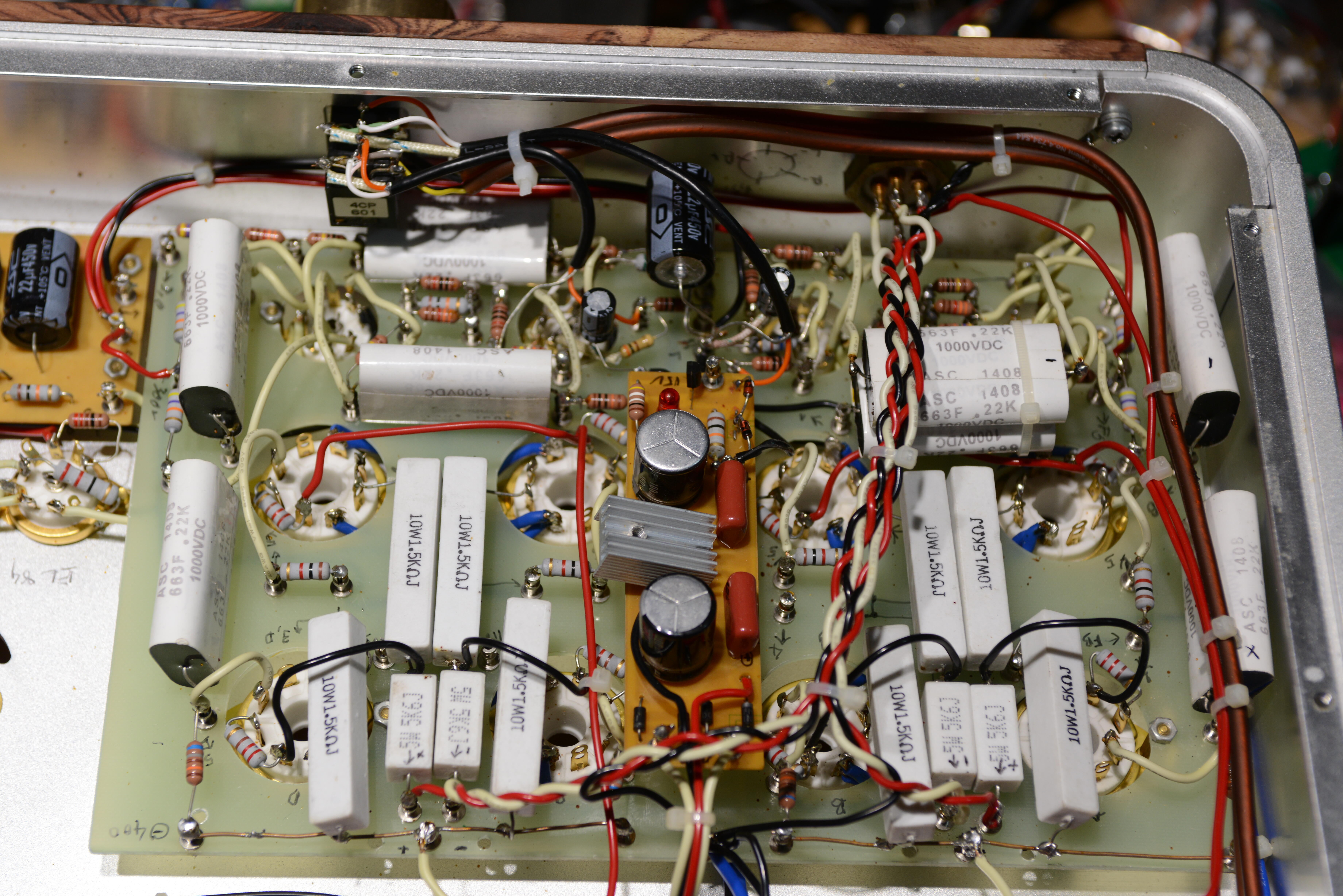
a quick game than anyone other than birgir or orientexpedite can play. look at the amp board above. now look at some of the other pictures of the real amp board. anyone know the 4 required major components that are missing? First one gets 10 booby points. hint: https://www.head-case.org/forums/topic/10783-megatron-electrostatic-headphone-amplifier/?do=findComment&comment=551186