kevin gilmore
-
Posts
7,120 -
Joined
-
Last visited
-
Days Won
21
Content Type
Profiles
Forums
Events
Everything posted by kevin gilmore
-
This one is for steve, i found it searching for a new bigger solid state hard drive

-
http://gilmore.chem.....edu/ebony2.jpg http://gilmore.chem.....edu/ebony3.jpg http://gilmore.chem.....edu/ebony4.jpg i managed to find a bullseye again.Too bad its so hard to see. And also a defect inside the wood. Its rough cut, ready for micro machining
-
Do it the same way i did with the T2. Angle bracket to a heatsink. Lots and lots of companies do this.
-
Yep, the real stuff, and aged about 50 years. Tree had to be a couple hundred years old. Its very hard to find a piece big enough to make knobs out of. Yes i got clobbered both on the price, and on shipping.
-
Messing with the input tubes can cause significant DC output which requires a pair of DVM's and a strong heart to adjust. The T2 is not like other tube amps. Best left alone. The wood is for more knobs. At some point i'm going to try and make a knob with the display inside it. Similar to the one on my Wolf range. And it will work the same way. Or maybe like that new thermostat from the ex-apple people, except made out of ebony.
-
I doubt he is using stuff this good. Or this size. Or this well aged. If he is, i sure was not able to get any from him. I've been looking for a piece that size and color for almost a year now.
-
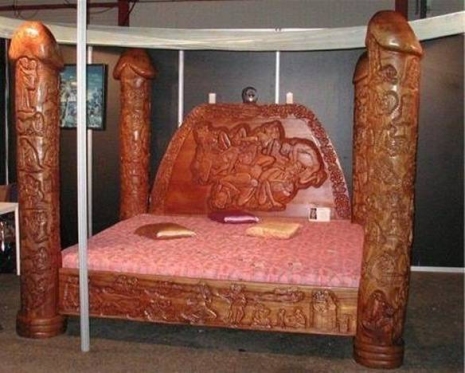
Speaking of phallic things, picture posted in the T2 thread. I may actually go in christmas eve and bandsaw the thing into appropriately sized cylinders, then stick in the lathe. I thought the lignum-vitae was dense, this stuff is 3 times more dense. Glad i have a new set of carbide bits.
-
I was not really planning on going into work next week, but this has changed my mind. http://gilmore.chem....n.edu/ebony.jpg 1500 grams, 8 x 2.5 x 3.5 inches about 50 years old.
-
Steve's humor alludes me sometimes. Now i see the smiley. need more coffee.
-
I owned an original pair of ohm-A's many moons ago. I did not think they got that low in impedance, otherwise they would have smoked the amp i had them hooked up to. Quads esl57's were 16 ohms i think, i have a pair in the basement i will have to look. Esl63's were about 2 to 3 ohms when the protection circuit kicks in. With 1 ohm speakers, the impedance of the speaker wire becomes significant.
-
translation: All of my products have one or more tubes in them, and are therefore not DC coupled from input to output. But wait, Lamm needs to examine the LF schematic for how to do DC coupled tube/solid state hybrid. Or he needs to talk to mikhail for how to do AC coupled fully solid state (the square wave) Bizzare specs, a power amp that puts out the same power at 8 and 4 ohms, then doubles the power for 2 ohms, and then again at 1 ohm. Anyone know any 1 ohm speakers?
-
Other than the T2 which is a special case, i publish the schematics and i give away board layouts that i have done. Anyone can take the schematics and produce their own boards if they want to and sell them as boards, kits, or completed units. And even the layouts i have done. I do however like to know whats going on, and kept in the loop. This is to try and avoid another trevornetwork superglue and plexiglass incident. The T2 is strictly non-commercial use only. Although the board files and schematics are available to anyone. No one with half a brain should consider building and selling T2's commercially. The north central Illinois Head Case Legal Group (that would be doug) has a significant amount of information on "FAIR USE" This would even include releasing for example a SACD DAC that takes an un-encrypted stream, with the information on how to modify specific players to generate such stream. However SONY et all won't pay attention to any of that and will sue your ass into the ground anyway. If you exactly copy a copyrighted circuit board layout without permission, you are violating copyright law. If you take the same exact circuit and do your own board layout, and it is not "familiar" to the other copyrighted design then its legal. Fact is that the LF schematic if you replace the tubes with a pair of jfets and a current source, looks absolutely identical to stuff seen in the late 1970's. So take a $50 circuit, put in a pair of tubes to make it look purdy, slap it in a box with glass windows, and abracadabra $3200 amplifer. Alex would not be the first to do this. He won't be the last either. Never mind what the distortion characteristics, or any reasonable specifications might be.
-

KG Balanced Dynahi build discussion thread
kevin gilmore replied to Vortex's topic in Do It Yourself
There is a missing resistor on the gates of the fets from the drive transistor, requires a cut on the circuit board and attaching a 1k resistor. schematic updated. like this http://gilmore.chem.northwestern.edu/dynapowerfix.jpg -
You can be sure that there will continue to be DIY amplifiers. The current transistors will continue to be available for at least another year. ixys has 1500 volt n-channel mosfets that sound just fine. The only difference will be a stronger drive circuit to drive the extra gate capacitance. I'm playing with this now. Its really just the 3rd stage voltage gain section. Standing power will go up a few watts per channel. Whats a few watts among friends
-
It should be noted that pete while not mentioning names specifically says that you need at least 70 volts on 6922's to get them to operate in a very linear region. 30 volts just does not cut it and requires much more feedback. Its tricky to make fully dc coupled dynamic amps with the input tube at 70+ volts. Something alex has not figured out yet. I suggest that alex look at the T2 schematic for some inspiration.
-
why does the simple stuff have to get so complicated sometimes.
-
I will attest to the fact that tyll was drinking 12 ounce glasses of cask strength whiskey. more than 4 on saturday for sure. Whether or not he was drunk was debateable, but he sure was happy.
-
That is the heatsink i want. Have not figured out what it is yet.
-
Hot Dougs in Glenview. Duck fat fries. botique hot dogs. Yummy.
-
And 6 additional parts. Tyll has said that he will be measuring amplifiers in no more than a couple of months.
-
All i can answer to is what i do. Justin sells some of my designs. When i buy stuff from him, i pay exactly the same price everyone else does. For example the pico dac. The rubber feet... A few circuit boards... Justin on ocassion does sell his circuit boards to others, he does not restrict who can buy them. I do other stuff too. And i'm fair about it, when its ready, everyone gets to see it at the same time. And i give away everything, to anyone. No hidden super secret special version bullshit. Now all of a sudden NoNoNoNoNoNo has access to several "DIY" LL board sets. Anyone else have access to those boards? Will alex sell any boards to anyone else, highly unlikely. If NoNoNoNoNoNo builds only the one, and keeps it for himself, that is one thing, but if he builds a few, then clearly there is something fishy going on here. I'm birgirs shipping agent for the USA. He buys stuff, sends it to me, i pack it correctly and ship it to iceland. Chicago to Reykjavik is about 4 days faster than NY to Reykjavik. Why, i have no clue. Birgir sends back tasty things loaded with sugar. VERY TASTY THINGS. In the process i get to listen to stuff that i would never have considered buying. And when i listen to something kickass, i go and buy it shortly afterwards. Like the LCD2's. Other than Sennheiser, i don't know of any headphone amplifier company that has high end test gear. The stuff is expensive and hard to maintain. I own some very nice test gear. Tyll owns some very nice test gear. Audeze owns some very nice test gear. Pete probably has access to the good stuff too. Alex says he designs stuff with just a voltmeter. Measuring distortion and other characteristics of an electrostatic amp requires special high voltage attenuators that have to be calibrated. Otherwise your test gear gets french fried. In the interest of full disclosure, blubiss sends me freshly roasted coffee beans. Which i have become addicted to.
-
And NoNoNoNoNoNo posts a pic of his DIY LL over there. Soon to be for sale at 3 or 4 times the parts cost
-
Yes of course i can mill down the heatsinks. I want something that others can build with no trouble. The heatsink fins need to be vertical to be efficient, so that ohmite thing probably won't work, but i can buy a couple from mouser next order to see. The other problem is that the lme49830 part would sit very low on the heatsink so the clips probably don't work. Which is why the original part i picked works poorly as the supplied snap clip only touches half of the part.
-
The woo stuff is built for a specific price point as is just about everything else these days. The transformers are appropriately sized, and none of mikhail's famous 800 volt stupidity. And none of the 25 ampere DC filament things either. So they are not going to blow up, or cause a fire etc. The issue with putting big caps after a tube diode without a large choke in the middle puts much more strain on the diode than is normal. So they don't last as long and eventually sag quite a bit. Meaning the resistance of the diode goes up permanently. Mercury rectifier tubes are something different entirely, are very low impedance, can work at thousands of volts, are still used today in some applications, and are toxic if you break one. It is possible to do a fully regulated all tube power supply. Tektronix did it by the tens of thousands. You need a tube rectifier (5u4), a pass tube (6l6) a gas tube voltage reference (0a3) and an error amplifier (6au6). No one seems to want to do it right. In fact if you do it this way, you don't need huge hunks of iron and stacks of expensive black gate caps either. So it could be way better, and way cheaper. But it does take up a bit more space. It would end the "my rectifier tube sounds better than your rectifier tube" sillyness. Remember mikhails "fully regulated" ESX power supply with the 10 gas tubes on top. This is the WRONG way to do a regulated power supply. I doubt that any of those lasted more than a few days.
-
Need to get rid of about 1 watt max. Width of chip is .75 inch. Would like a single sided thing with circuit board mount pins that is about 1.5 inches wide, .5 deep and 1.5 inches high.