kevin gilmore
-
Posts
7,131 -
Joined
-
Last visited
-
Days Won
21


kevin gilmore's Achievements
Super Secret Ultra Gold Member (6/6)
2.4k
Reputation
-
150ma for -60 50ma for -250
-
150ma spec for +/-500 50ma spec for +/-250 150ma spec for -60 50ma for +/-15
-

Megatron Electrostatic Headphone Amplifier
kevin gilmore replied to kevin gilmore's topic in Do It Yourself
quotting shawn "I have some concerns if two modules can work in parallel. In Megatron XL, the two 300Bs per channel share the same filament supply" no they do not. each output tube (all 4 of them) has its own filament supply. they have to be seperate supplies for the 300b because they are in the audio circuit. in the d&g i use 2 switching modules in series to get the equivalent for 10v. -
Megatron Electrostatic Headphone Amplifier
kevin gilmore replied to kevin gilmore's topic in Do It Yourself
so that chassis in various sizes was available on ebay. i do not know whether it is still available. will have to look later. i know that some people think the tent labs filament supply is gods gift to dht tubes. real fact is that it does not really like hanging off -450v. as it was never designed to do so. there are better, cheaper and smaller ways of doing this. -
finally an electrostatic transportable
kevin gilmore replied to kevin gilmore's topic in Do It Yourself
you are aware that you need a heatsink touching all the sot transistor. still with heatsink it typically can take about 5 minutes to reach high temps. -
finally an electrostatic transportable
kevin gilmore replied to kevin gilmore's topic in Do It Yourself
i am aware of the overheating issues. i have an assembled board coming to me to look into this. something clearly has changed from the original parts i used and there is some positive thermal runaway that did not happen with the prototype. there is a later version board now, 4 layers, still does not fix the problem. putting 12v zeners in series with the 1.1meg resistors may introduce enough negative thermal compensation. otherwise the bias needs to be trimmed a lot. hate the parts situation i do. -
Feliks Audio Bliss - so much stupidity...
kevin gilmore replied to spritzer's topic in Headphone Amplification
can't find any internal pictures. but a 6ca7 as a current source for a 300b has plenty voltage swing, more than 1600 volts is possible. but the front end is lacking in voltage gain. so you are definitely going to need one of those 10v output dacs. -
you forgot the dn2540 cascode on the 10m90s
-
finally an electrostatic transportable
kevin gilmore replied to kevin gilmore's topic in Do It Yourself
updated board file, 10k input resistors added (optional) and 25k changed to 17k cfaelectrostatschem2-4 - CADCAM.ZIP -
the neutrik jacks i used in the diy t2 are actually 4 wires. the connector shell is a seperate wire. i put in a jumper to chassis ground for that wire.
-
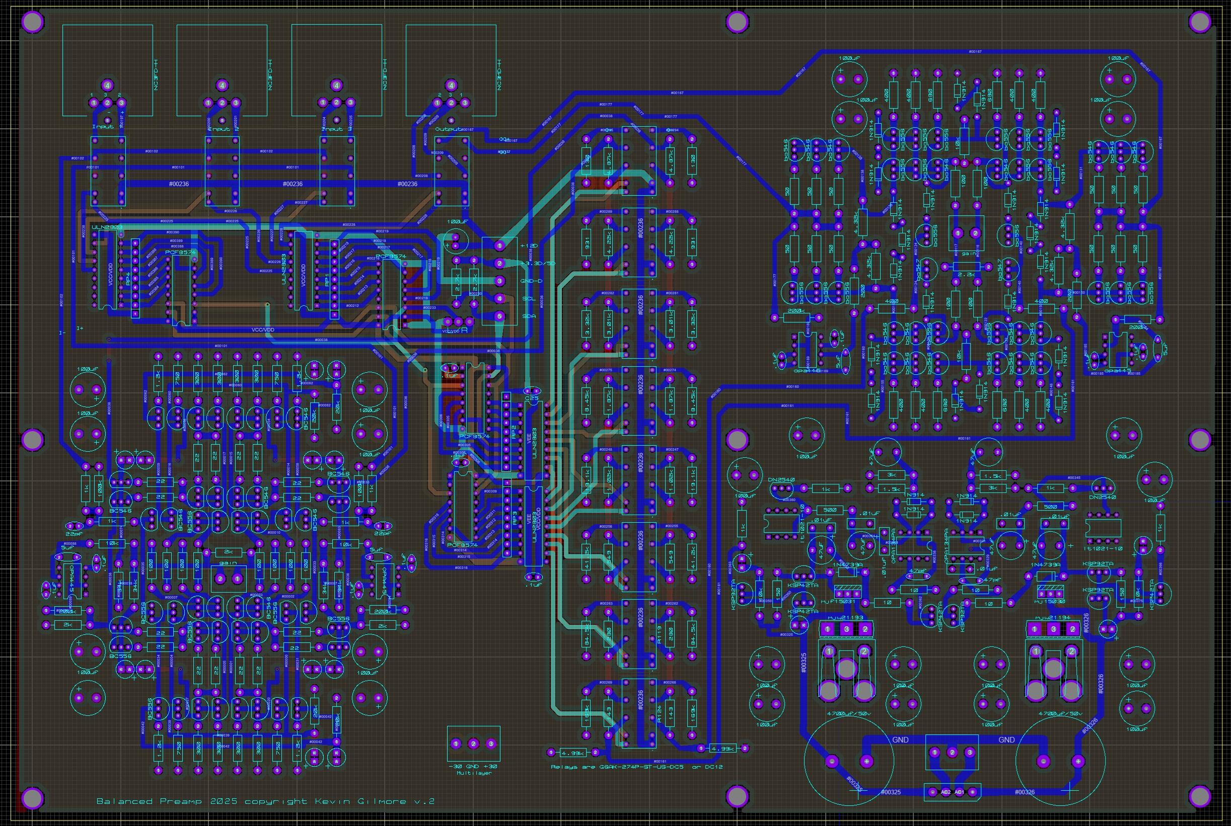
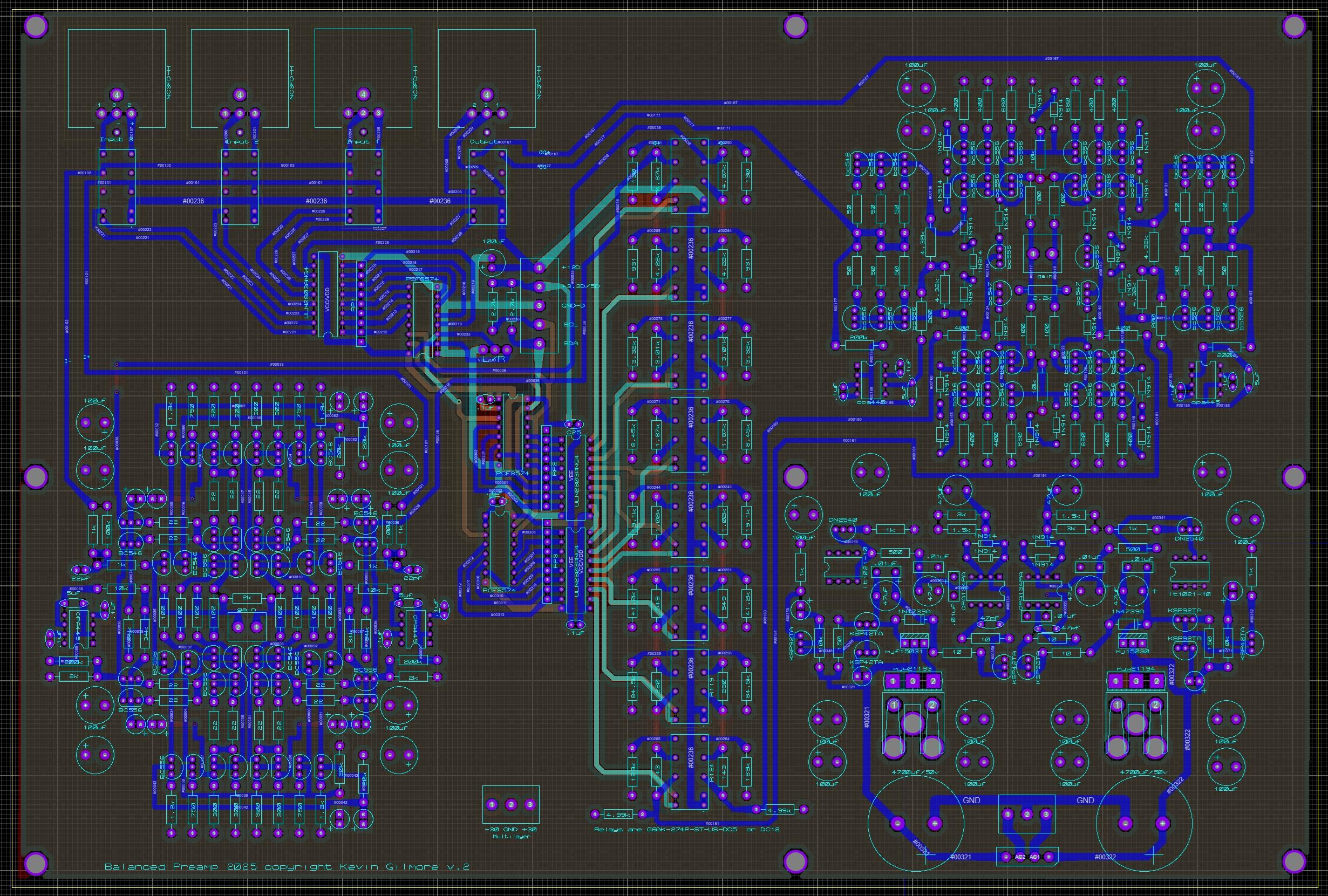
relays are dual coil latching. so 2 might be tricky. 3) lots and lots of cheap transistors. best to go with the "B" versions, matching is always better. 4) 50k attenuator NOT NEEDED. thats the point. there is no commercial product with an output voltage that will saturate the input. 5) very much like the ayre kx-r. individual resistor goes between the 2 pins. for increased gain should you want or need it. schematc shows everything at 0db gain.
-
only need one power supply for both channels and its not a lot of power. also runs whatever microcontroller you decide to use.
-
possible final version, 4 inputs and the xlr jacks correctly located preamp2025i - CADCAM.ZIP
-
this version should be compatible with the amb lcduino software with no changes. preamp2025h - CADCAM.ZIP

-
soren asked for the board with onboard grlv preamp2025g - CADCAM.ZIP preamp2025g.PDF