dsavitsk
-
Posts
4,776 -
Joined
-
Days Won
65
Content Type
Profiles
Forums
Events
Everything posted by dsavitsk
-
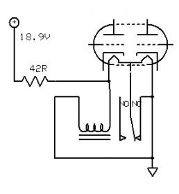
For shielded tubes, you can AC or DC couple the shield to ground. I've done both, and both seem to work OK. So, you could just AC couple it (100n is fine) and then it should be fine with CT or not CT tubes. For a more complicated solution, use an 18.9V supply and a 42R resistor in series with the heater. Then, 12.6V/150mA tubes (12**7) will drop 6.3V across the resistor while 6.3V/300mA tubes will drop 12.6V across it. You could add a relay, as well, that would connect the CT to ground in the event that it is supplied with 12.6V. The drawback here is that you are limited to 12.6/150 and 6.3/300 tubes, which may be a limitation you are unwilling to make. There is only one 12V non-ct only tube that I know of, but it is a secret. Send me a PM and I'll tell you about it.

-
Looks to me like 1/4" minus the thickness of the extruded bottom which I'd guess to be about 1/16".
-
So long as you don't drop them, they are fine. The biggest issue is that the mercury condensates and settles over time, so the first time you turn them on, you have to just power the filament and let them sit for a while (~30 minutes or so I think) to re-evaporate the vapor. There is also the issue of PS input caps, and they are really meant for choke input supplies. Choke input supplies are fine, but they are more expensive to implement and often hum unless you really oversize the choke. They also glow real pretty. That said, I won't use them. Other than the light show, there isn't any real benefit to them (if you can hear the difference from one rectifier to another, you have a poorly designed power supply ...) and while the risk is small, it is there and I prefer to keep the toxins out of my living room when I can. I have broken enough tubes in my life to not want to deal with it. Other things that may expose you to mercury ...
-
Do you have a pic of how they came out? I am thinking about using them for this but am a little unsure of the quality.
-
How about FPE? It costs a little more, but you can make them any size you want. If it is only for a few, it seems like a decent deal.
-
Not one to leave well enough alone, I thought I'd tinker a little more. The obvious next thing to do was to swap out the last PS cap. I had used a Blackgate Std, but these aren't my favorite caps, and I figured a film cap would be better. To that end, I removed the Blackgate and added a big Motor Run film cap. These are just big polypropylene caps dipped in oil of some sort. This improved clarity a little, but unfortunately it also lost some bass. The usual solution to not enough bass is bigger caps. So, I got a bigger cap.
-
I used to work at a used camera dealer (let me tell you about the stack of Nikon S1's we had ...) and AE-1's were everywhere. I always found the frame advance felt like it was grinding the film to shreds, and the FD lens mount was awkward. Consequently, we couldn't sell them. We didn't see all that many Nikons, but the old OM stuff was some of my favorite. Personally, I like to use either Olympus Pen stuff now, or else my Contax G which was really cool when it came out, but not so cool now that Contax is once again extinct
-

the NEW Zana Deux, ZDT and Balancing Act thread
dsavitsk replied to oatmeal769's topic in Headphone Amplification
In general, in a standard single ended "300B" amp, assuming that everything is reasonably done, the things that influence the overall sound from most important to least important are ... 1. topology (including the power supply) 2. quality of passives and iron 3. quality of driver tubes 4. the 300B's Western Electrics may well sound a lot better than Valve Arts, but I'd take a well designed amp with good iron and caps and cheap tubes over a run of the mill amp with WE outputs any day. As a matter of fact, I have 300b amps with good iron, a good topology, and extra cheap tubes. They sound great. -
Isn't this what insurance is for? You can get some big output caps for cheap to put between it and the speakers for testing if you are concerned that it will spew DC. Or, get some 8R 5W resistors and put those across the speaker terminals (instead of speakers). Then, assuming no smoke comes out upon turn on, use a cheap multimeter to measure across the resistor for DC. If there is none, download a 60Hz tone, play this through the amp, and measure for AC across the resistor. if you get AC but no DC, then hook it up and give it a listen. 70's solid state gear that's even worth $2K? I am having trouble envisioning it. I agree with Nate that I'd open it first and see if anything looks corroded.
-
The design uses a balanced dac chip, has balanced outputs, and uses a single tube. That tube only has two grids, two circuits, which means that these numbers don't add up. This suggests that either the tube is not actually part of the signal, of that the output is converted from balanced to single ended and then the tube is being used as a cathodyne phase splitter to make it balanced again. Also, the headphone out looks like a single opamp.
-
That's what mine are. I have soldered and modified a fair number of things in my life, yet cutting the end off my headphones still made me nervous.
-
What standards are people using for reterminating these? I'm planning on a single 4-pin XLR rather than 2 3-pin as it is less cumbersome. Does a male connector on the phones with pin 1 for R+, 2 for R-, 3 for L-, and pin 4 for L+, and 2 and 3 connected together for use in single ended amps sound right? Also, anyone know the stock Grado wire colors before I cut this thing apart? If it matters, these are RS-1's bought about 6 years ago.
-
Why is the power button not centered top to bottom? It looks awkward where it is. Also, does it need to say "power"? Are you going to forget what it does?
-
the NEW Zana Deux, ZDT and Balancing Act thread
dsavitsk replied to oatmeal769's topic in Headphone Amplification
In theory, theory and practice are the same, but in practice ... Yes, I basically like a high load for a tube and no cap in the cathode. The design is clever in a lot of respects, and there is much about it to like, but in a cost for sound calculation, I'm not sure I agree with their choices. Here are some issues ... Chokes present a load to the tube that is 2*pi*Frequency*Inductance. There are two things to note about that. The first is that the load is rising with frequency. This is not necessarilly a problem so long as the choke is sufficiently large, but at the margins it can be an issue, particularly with high rp tubes. The second is that the choke is just too small for the tube in the first stage. They are loading a 6J5 with a 200H choke. The 6J5 has a rp of ~7K. The higher the load on a tube the better, but you really want it to be at least 4 to 5x rp. At 60 Hz, that choke gives a load of ~75K which seems pretty good. However, at 20Hz, it is only 25K which is a lot less good. Moreover, that diode has an impedance of around 200 ohms at these currents. This, as you know, is multiplied by mu and added to rp. So, rather than 7K, rp is actually ~11K meaning that that 25K load is really on the borderline, and deep bass is likely to suffer considerably. In contrast, the LEDs in yours (which are diodes as well) have an impedance or about 8 ohms, and the load that we put on the tubes is about 10M, even at 20Hz. In fact, the limit to yours comes fro the Miller capacitance of the output tube which is a different issue altogether. Anyhow, this really comes down to the 6J5 being a poor choice of valve -- a D3a, for instance, solves much of this. The advantage of a choke over a CCS is that it can swing above B+, but that does not seem to be the issue here, at least in the first stage, as the grid will hit cutoff long before that point. So, a CCS on the first stage with a better biasing scheme would likely be a good thing. Oh, and the PS has a little more ripple and a lot more sag than I think you'd want -- and in simulations, it might destroy the rectifier. Why they didn't use damper diodes there instead of in the cathodes is a bit of a mystery. Edit: I should also add that iron resonates, and that much iron is likely to resonate in unpredictable ways. It may not be an issue, but it is likely not an amp that you could just build as drawn without some sophisticated measurement equipment and just expect it to work. -
the NEW Zana Deux, ZDT and Balancing Act thread
dsavitsk replied to oatmeal769's topic in Headphone Amplification
It's a big topic. These are probably as good as anywhere to get started: [url=http://www.sixmoons.com/industryfeatures/distortion/distortion.html]6moons.com - industry features: "Distortion & -
the NEW Zana Deux, ZDT and Balancing Act thread
dsavitsk replied to oatmeal769's topic in Headphone Amplification
Lots of things have turned the amp world on its head. Feedback, transistors, Class B, Class D, etc. Maybe OTL is among them. That doesn't mean that these things lasted, or that the long term evaluation is necessarilly good. It also doesn't mean that they are bad. I am sure there are plenty of wonderful OTL amps out there (well, I'm not actually sure of that, but for the sake of argument I'll stipulate to it), but OTL is too generic of a description to necessarilly mean much. There are certainly bad ones too. Me, I often use transformers as I find the designs I make with them to be both intellectually interesting, and good sounding. But, you'll find that others disagree. -
the NEW Zana Deux, ZDT and Balancing Act thread
dsavitsk replied to oatmeal769's topic in Headphone Amplification
The primary reason for good tube sound is that tubes are very linear devices. Transformers are useful things, and when correctly designed and implemented, will do little damage to the signal. Transformers get a bad rap because good ones tend to be expensive. You have your decades wrong. The poor designs are from the 50's. Transformers were, by then, old hat. Oh my. -
DNA (Donald North Audio) Headphone Amp
dsavitsk replied to blubliss's topic in Headphone Amplification
You mean to say that there are people selling snake oil to audiophiles? By the way, don't take my comment that the Jensen electrolytic cap fits to be an endorsement of Jensen electrolytic caps. I've never used one and consequently I have no opinion of them. My preference would be a large film cap of some sort, but those likely won't fit in the existing hole. Most tube power amps, at least those built with a modicum of safety in mind, have the speaker returns connected to ground. -
DNA (Donald North Audio) Headphone Amp
dsavitsk replied to blubliss's topic in Headphone Amplification
There is the "signal" path, and then there is the signal path. The big JJ and the cathode bypasses are both in the signal path and will have a large influence on sound. You can buy that cap at Parts Connexion on sale for $50 right now, and the soldering will take you about 10 minutes. It looks like it is even the same diameter so it should fit the chassis nicely. -
DNA (Donald North Audio) Headphone Amp
dsavitsk replied to blubliss's topic in Headphone Amplification
Tubes are, it turns out, extremely linear devices. The warmth and poor frequency response often attributed to them has more to do with topology and other components than the tubes themselves. -
DNA (Donald North Audio) Headphone Amp
dsavitsk replied to blubliss's topic in Headphone Amplification
Doesn't that suggest that it is capacitor warmth? -
I don't think it adheres to any standards. They basically drew it with a sharpie and used jumpers and bits of wire to connect things -- you should see under the board. Yeah -- I think it is a 2mA jump.
-
Thanks. It's a tough call as to how much work to do on one of these. Certainly, one could use all V-Caps and Blackgate NXes, build some super duper fancy regulator, rework the solid state power supply, etc. But, the circuit has inherent limitations, and I tried to stay within them and not let this get out of hand. Though, those 2u caps may get replaced with something a little better.
-
Not true. Here's my DAC. You can thump on those tubes all day long with nary a peep.
-
I have been thinking about parting with my Melos SHA-1 for a while. It was [url=http://www.stereophile.com/headphones/617/]Corey Greenberg