Leaderboard
Popular Content
Showing content with the highest reputation on 09/16/2024 in all areas
-
6 points
-
5 points
-
5 points
-
4 points
-
2 points
-
2 points
-
2 points
-
If anyone is interested who Raymond Kohn is, who signed the car. This guy: (also the people seem a little close)2 points
-
2 points
-
2 points
-
I was on a boat That crossed the bay To "The City" Where we had a guided tour by a retired lawyer of the TJPA/Salesforce Transit Center and Rooftop Gardens Then saw some art And took the new subway (only $1.9B) to Chinatown, for their night market. And then a short rest* Before taking the ferry home again. *The more eagle eyed of you will spot the token foreground interest, bottom right.2 points
-
1 point
-
1 point
-
1 point
-
much better. max sensitivity of the qa403. 60 hz and multiples are very hard to remove, moving wires around in the box and things will change. completely inaudible. the synchronous rectifiers may take out even more noise. mumetal shielding around the transformer is also a good idea. glad that more and more people are buying the qa403. higher quality diy coming soon1 point
-
1 point
-
1 point
-
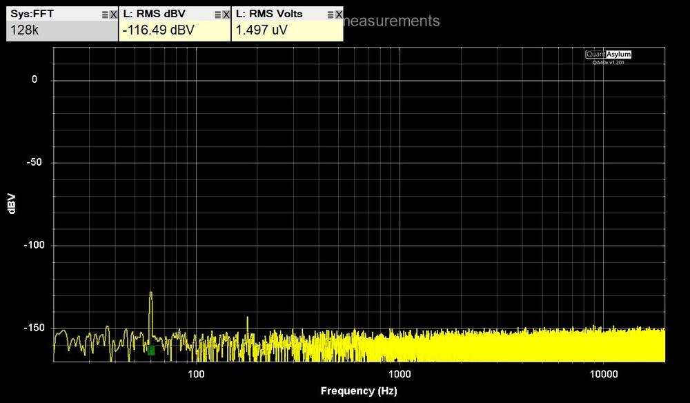
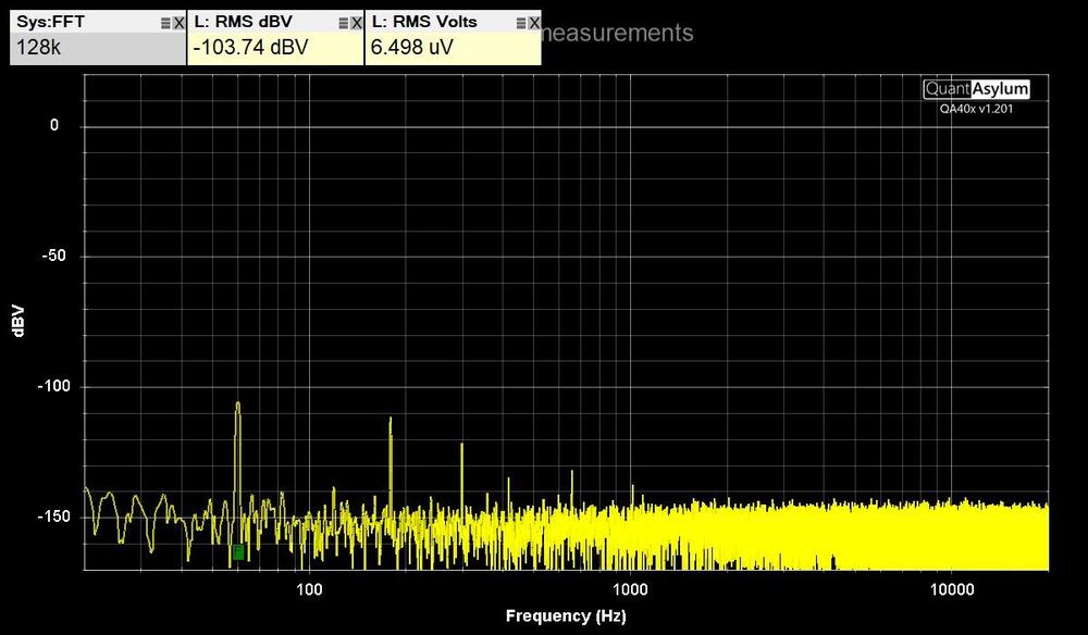
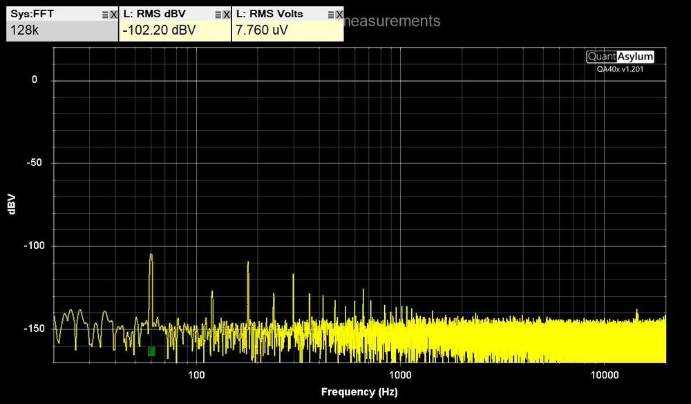
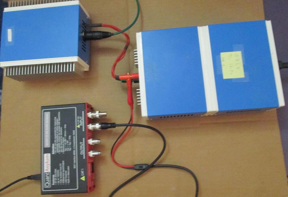
QuantAsylum QA403 tests Tested my GRLV noise level with the QA403 by connecting it directly with BNC test leads. The maximum DC input of the QA403 is 40 VDC. Measured the positive and negative voltages separately to see each noise level. Used the left positive input BNC and put a terminator on the negative input BNC. Installed software from https://github.com/QuantAsylum/QA40x/releases/download/1.201/setup_QA40x_1.201.exe Start app and Select File-> Devices-> QA403 Select File-> New Settings, Set the FFT size to 128k, the full scale input to 0 dBV, and hit Run. The first image is with the 36" BNC test leads alligator clips shorted together. The second image is the QA403 connected to the GRLV with no load. The third image is the GRLV with CFA2 as the load. Have less than 8 uV RMS Volts on each output. Was able to run RMAA on the QA403 by installing ASIO drivers. https://github.com/dechamps/ASIO401 Install https://github.com/dechamps/ASIO401/releases/download/asio401-2.0/ASIO401-2.0.exe Have to adjust the input/output scaling with the configuration file ASIO401.toml in the Windows user profile folder; for example: C:\Users\Your Name\ASIO401.toml Make sure the file doesn't have .txt on the end of it. My settings for the RMAA loopback cable tests are: fullScaleInputLevelDBV = +6.0 fullScaleOutputLevelDBV = -2.0 Adjust levels when testing an amplifier with gain. The input values can be: 0.0, +6.0, +12.0, +18.0, +24.0, +30.0, +36.0 and +42.0 The output values can be: -12.0, -2.0, +8.0 and +18.0 Install RMAA https://audio.rightmark.org/downloads/rmaa6.exe Right click and Run as administrator. Start it and select ASIO401 for input and output device. Select 24 bit and 48 kHz. Install four coax bnc loopback cables from output to input on the QA403. select Playback/Recording icon. start test if signal levels are good, otherwise adjust levels in ASIO configuration file. when test is done, save to location. Generate a RMAA test report with the paperclip icon. The test report has misspelled configuration signal as singal. I used hexinator app to edit the rmaa6 executable C:\Program Files (x86)\Rightmark\rmaa6 Select Edit, Find, singal at 496C00 Change the hex code 6E 67 to 67 6E and save. Here are the results of the RMAA balanced loopback tests in the last image. A picture of the QA493, GRLV, CFA2 is the fourth picture. The GRLV has the transformers in the rear box and the regulators in the front box. Two steel panels separate them to lower noise.1 point
-
1 point
-
I guess this gal is Linkin Park’s new vocalist? Good album! Dead Sara - Ain’t it Tragic1 point
-
1 point
-
The calculation are based on some assumptions and tradeoffs. Ideally you need to know some things about the high voltage power supply the secondaries will be powering. 1. you need to know the minimum voltage input to the power supply to get the required regulated output at the required current. (the minimum input will usually increase with higher current draw). typically this will be a fairly small additional voltage above the output voltage for low voltage power supplies e.g. a few extra volts for the golden reference low voltage and typically in the few 10s of volts extra for the golden reference high voltage power supply. Since this is the absolute minimum you probably want a little more input voltage than that to be safe. 2. the voltage out of the wall also varies. In many countries during peak demand the power companies can reduce the voltage - typically by up to about 5 to 10% so you need about 10% more voltage on the output side than you might think to compensate the electrical grid giving you less than you expect. So we multiply the total secondary output voltage by 1.1 i.e. add 10% 3. Competent transformer design is also assumed. The more current you draw from a transformer the more inefficient it becomes. Which is why you specify the output voltage of the secondaries at the current draw you expect. If the manufacturers are crap and only design the transformer secondary output based on no load being applied you can have issues where the psu loads the secondaries and the output of the secondaries drops so much you don't get enough voltage for the psu to maintain regulation. Conversely if the manufacturers design the transformer properly, specifying a transformer with a much higher secondary current draw than it will actually experience will result in the secondary voltage being higher than expected. Any voltage going into the psu above the minimum amount required to regulate will be converted into additional heat. Any voltage below the minimum to regulate will result in loss of regulation and the output voltage dropping with greatly increased levels of ripple and noise. you also need to make sure the input capacitors in the power supply can handle the peak voltage going into them or their life expectancy will be reduced and in more extreme overload conditions they can fail completely. (the output caps are mostly isolated from the varying input voltage and should only see the DC voltage output the power supply is setup to output assuming there is no failure in the psu which causes the regulation to be bypassed/short out and pass all the available voltage to the output e.g. the pass transistor to be fully switched on or become shorted) [Since minimum dc voltage input for regulation - DC output voltage] is the additional voltage needed to regulate at the required current draw. secondary VAC = (minimum dc voltage input for regulation *1.1 )*0.707 Or secondary VAC = ((DC output voltage + minimum additional voltage for regulation)*1.1 )*0.707 so if we assume 10V more input is needed to regulate than output for 400V output we get: secondary VAC = ((400+10)*1.1)*0.707 = 319VAC1 point
-
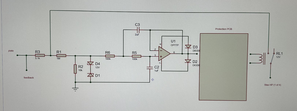
I'm going to try an electrostatic HP version of Kevin's balanced HP protector. I may keep all 4 outputs separate, using 1kV rated relays, which are usually single pole anyway. Plus this way each output could have its own status LED, which would show which of the 4 outputs (L+, L-, R+, R-) was triggered. Here is a preliminary idea:1 point


