All Activity
- Past hour
-
He’s back
- Today
-
In this economy?
-
Where is his chef’s hat? How else will he catch the egg in the hat?
-
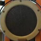
Very nice! 👍 They look very professionally made. What material do you use for dust cover?
-
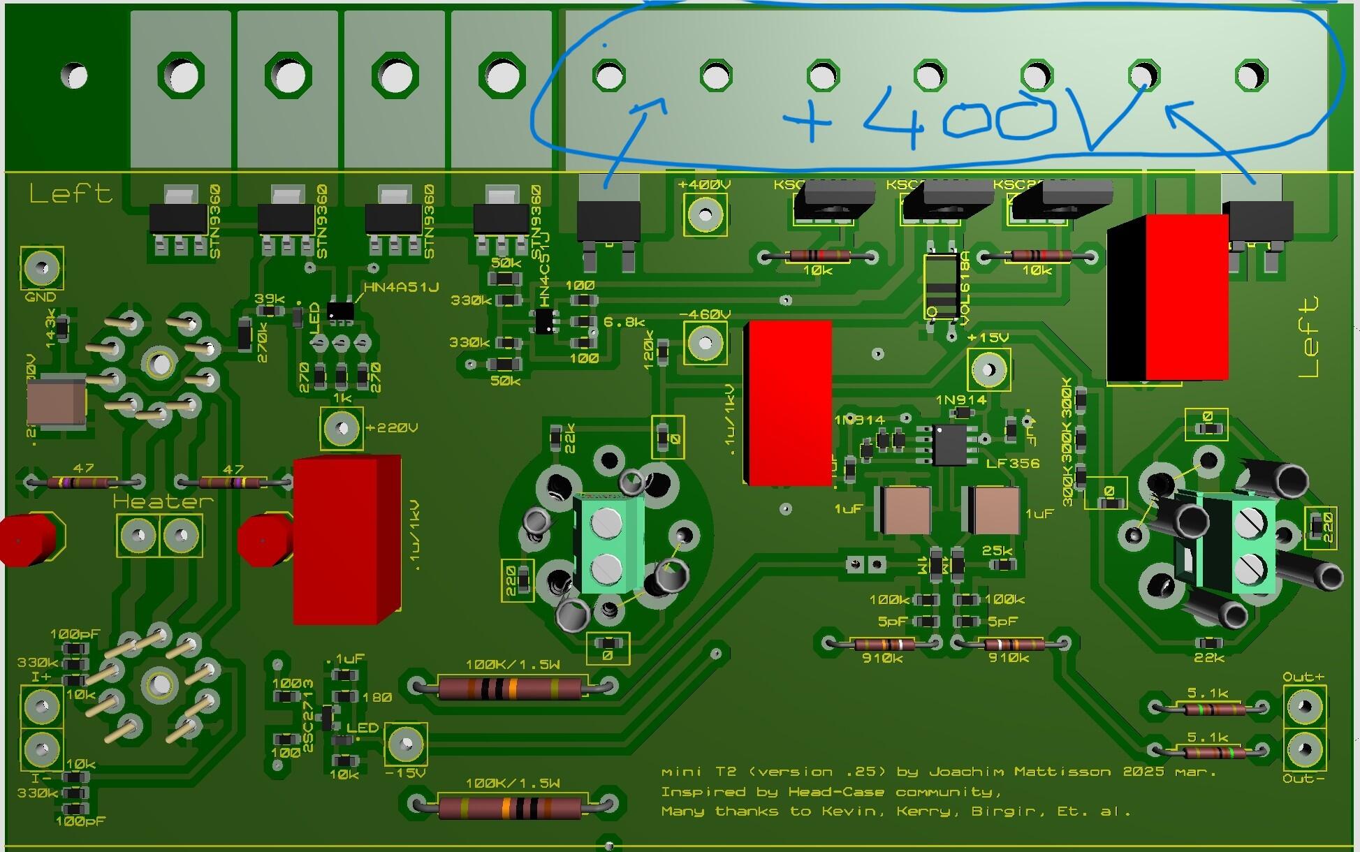
The layout referred to this(kgst-miniv05). Didn`t find the DN2540 in this version. DN2540 version added to the previous post. Q1 (MPSA/W06) can be replaced by 2SC3324. Q4 and Q6 (MPSW/A56) can be replaced by HN4A51. Q5 and Q7 (MPSA/W06) can be replaced by HN4C51.

- Yesterday
-
Those look stunning!!! If you ever want to sell one those, hit me up. I've been going over your writeup on the Shangri-la as I want to build a clone of them but naturally improved (as the stock ones are pretty terrible). Find a broken HE1000 or a Arya Organic should get me close to the same chassis and go from there.
-
I haven't heard either of these cello concertos. Worth your time if you like Shostakovich.
-
you forgot the dn2540 cascode on the 10m90s
-
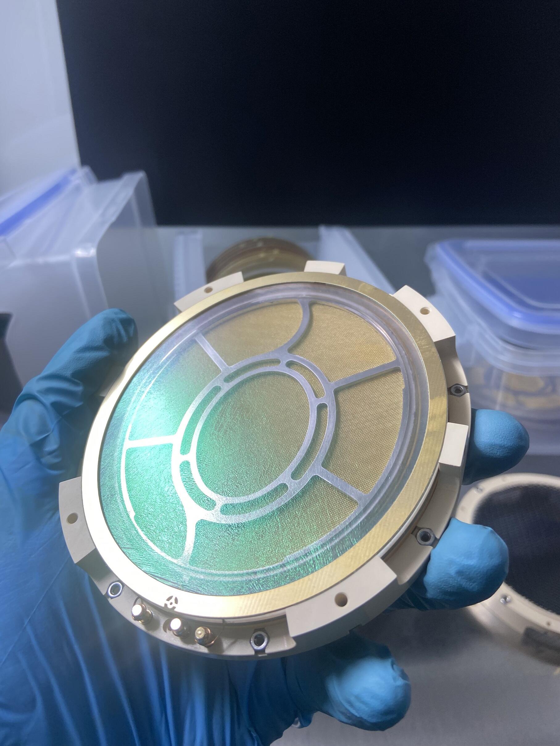
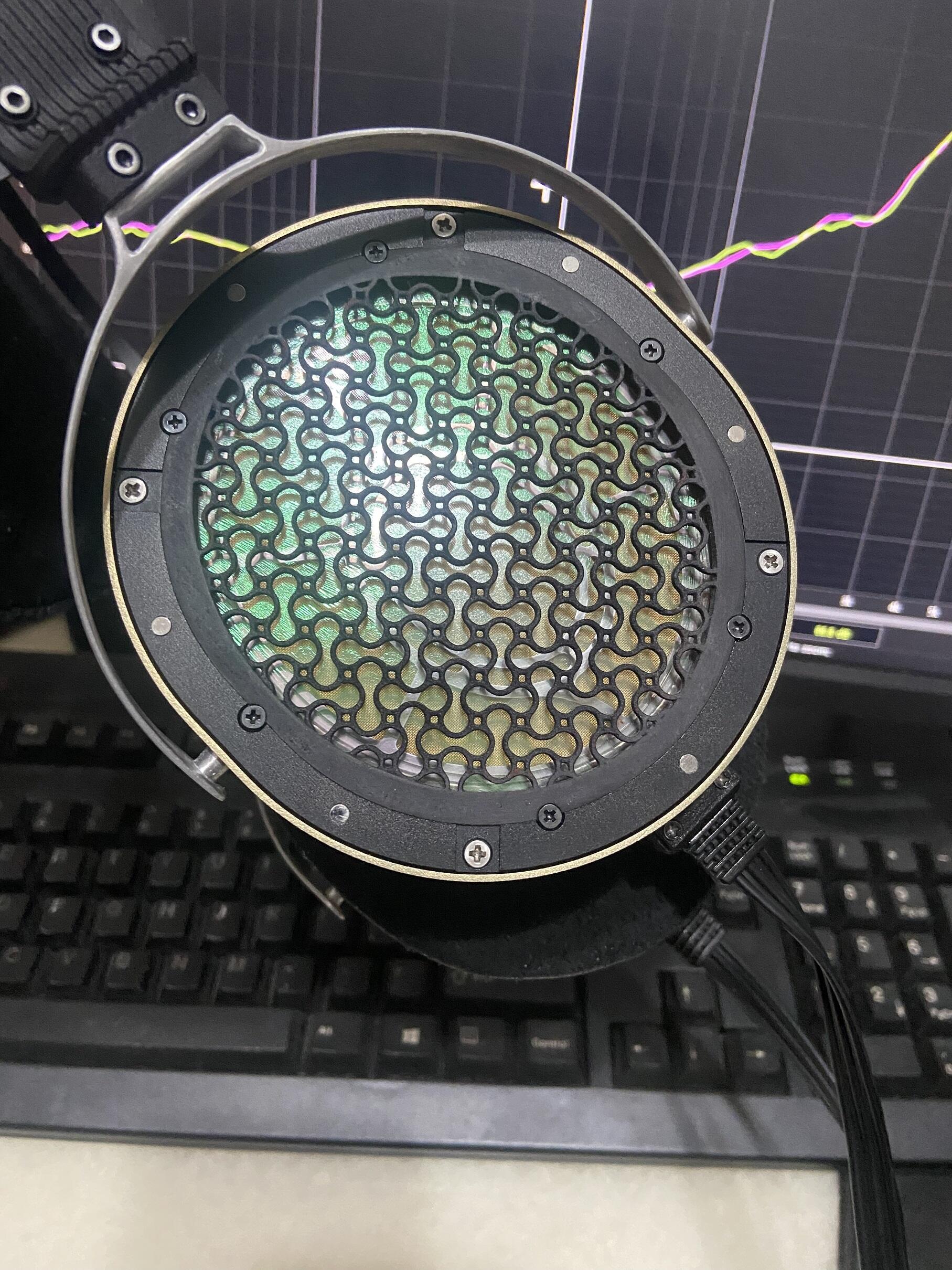
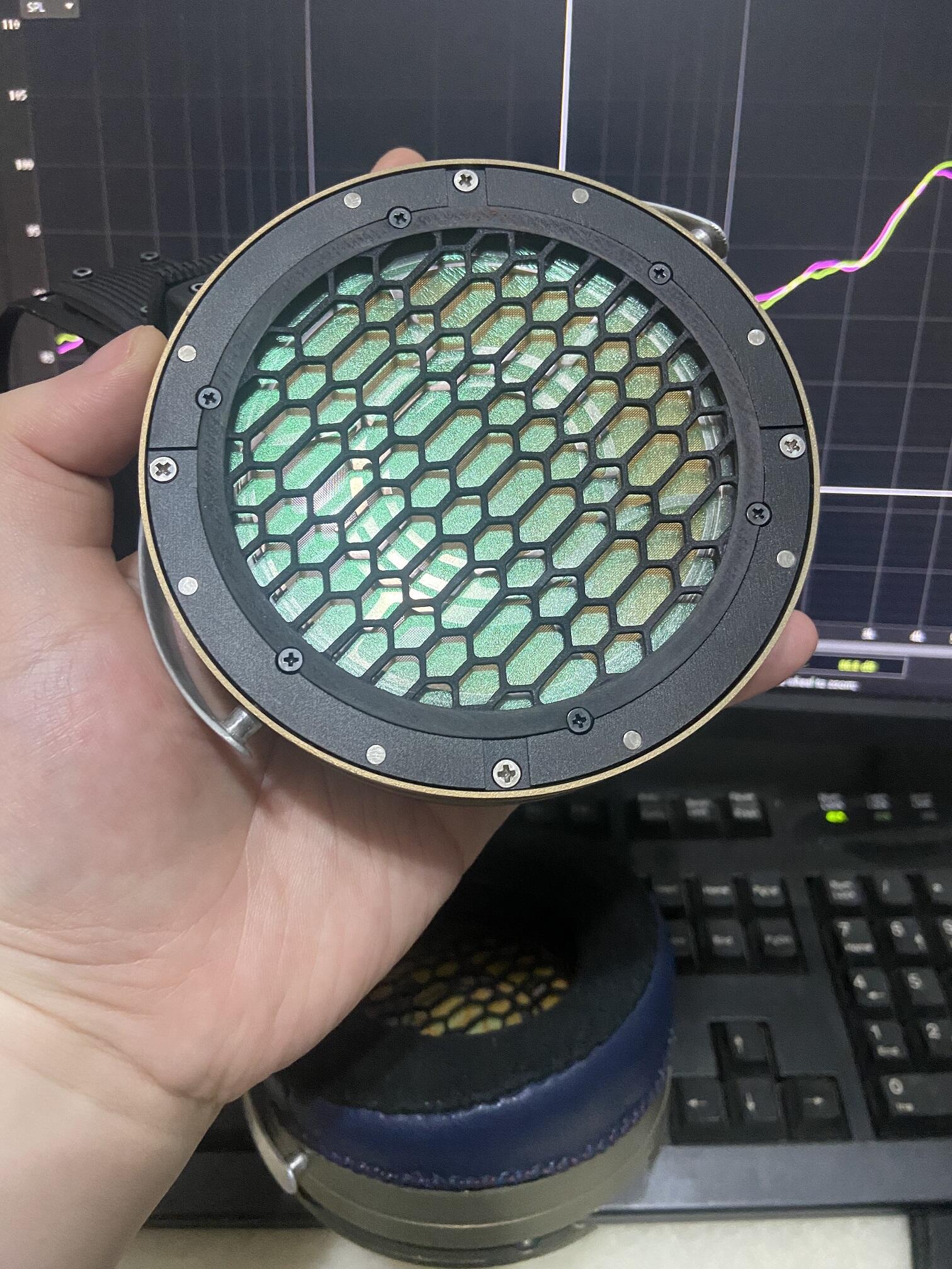
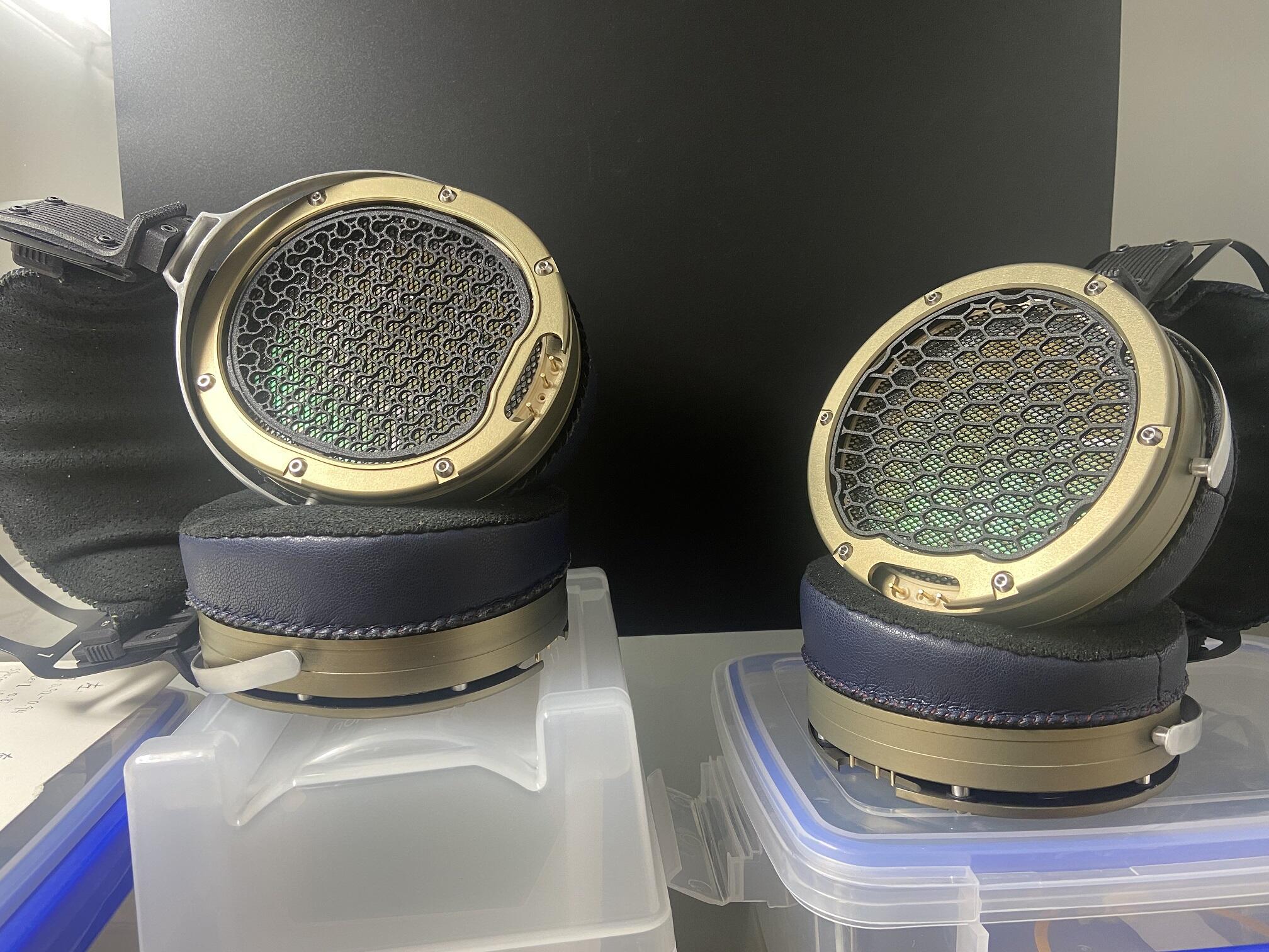
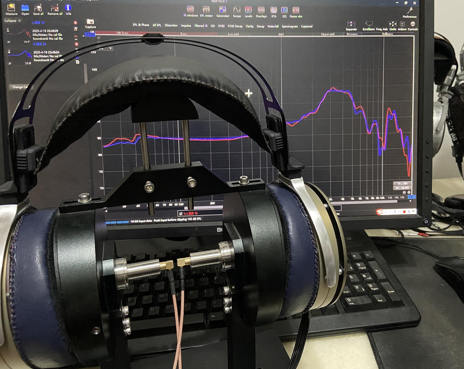
Long time no see, I have updated many different designs in the past few years. My estats are currently using an omega-like assembly structure but with a driver house made of PPS plastic, and shells are all made of CNC 7075t6 aluminum alloy + hard anodized. The tuning of my headphones has changed to a retro diffuse field target curve which is completely different tuning from stax that emphasizes 1-2khz and 4-6khz.I really enjoy the stax-style assembly method, which makes them look much more refined than German estats.
-
Stan Love has passed away. A basketball and music guy. Former NBA player and father of Kevin Love (hell of an NBA player). Mike Love's brother. He led an interesting life for sure. Thanks for fighting for cousin Brian. You literally kept him alive at one point. RIP, Stan. https://sports.yahoo.com/article/stan-love-nba-player-brian-174737737.html?fr=yhssrp_catchall
-

finally an electrostatic transportable
kevin gilmore replied to kevin gilmore's topic in Do It Yourself
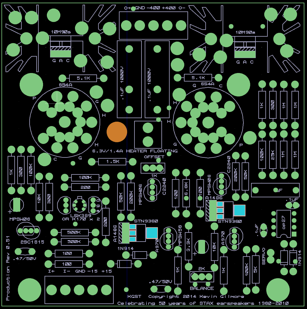
updated board file, 10k input resistors added (optional) and 25k changed to 17k cfaelectrostatschem2-4 - CADCAM.ZIP -
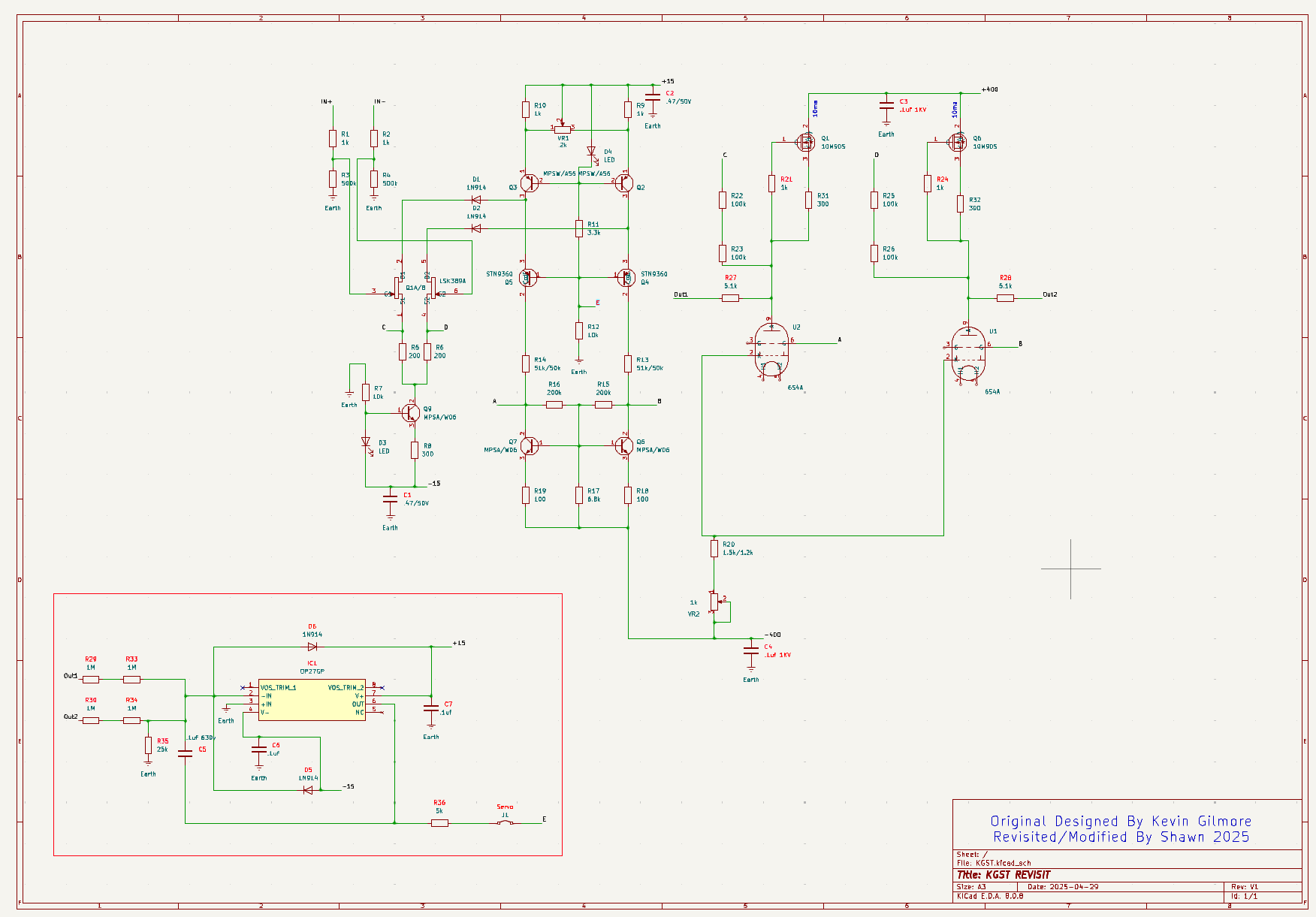
Time really flies — it's been over 10 years since the KGST first came out. KGST was one of the very first DIY electrostatic amps I ever built, and it's still one of my favorites today. Recently, I noticed that the schematic in the Stax Mafia Google Drive has diverged quite a bit from the latest version of the KGST PCB layout. So, I decided to take this opportunity to redraw the schematic based on the newest KGST layout. Hopefully, this will be useful to anyone who needs a fresh reference. Please double-check the schematic before using it — there might still be mistakes. Component numbers follow the original KGST schematic as much as possible. New parts are numbered sequentially. Changes from the old schematic are marked in red The servo section has been added Obsolete parts like C2240//A1486/2SC1815 have been replaced with currently available ones Attached below is the schematic. Next step: I'm planning to attempt a shrunk-down version of the KGST layout, inspired by @JoaMat great work. KGST_2025.pdf KGST_DN2540_2025.pdf
-
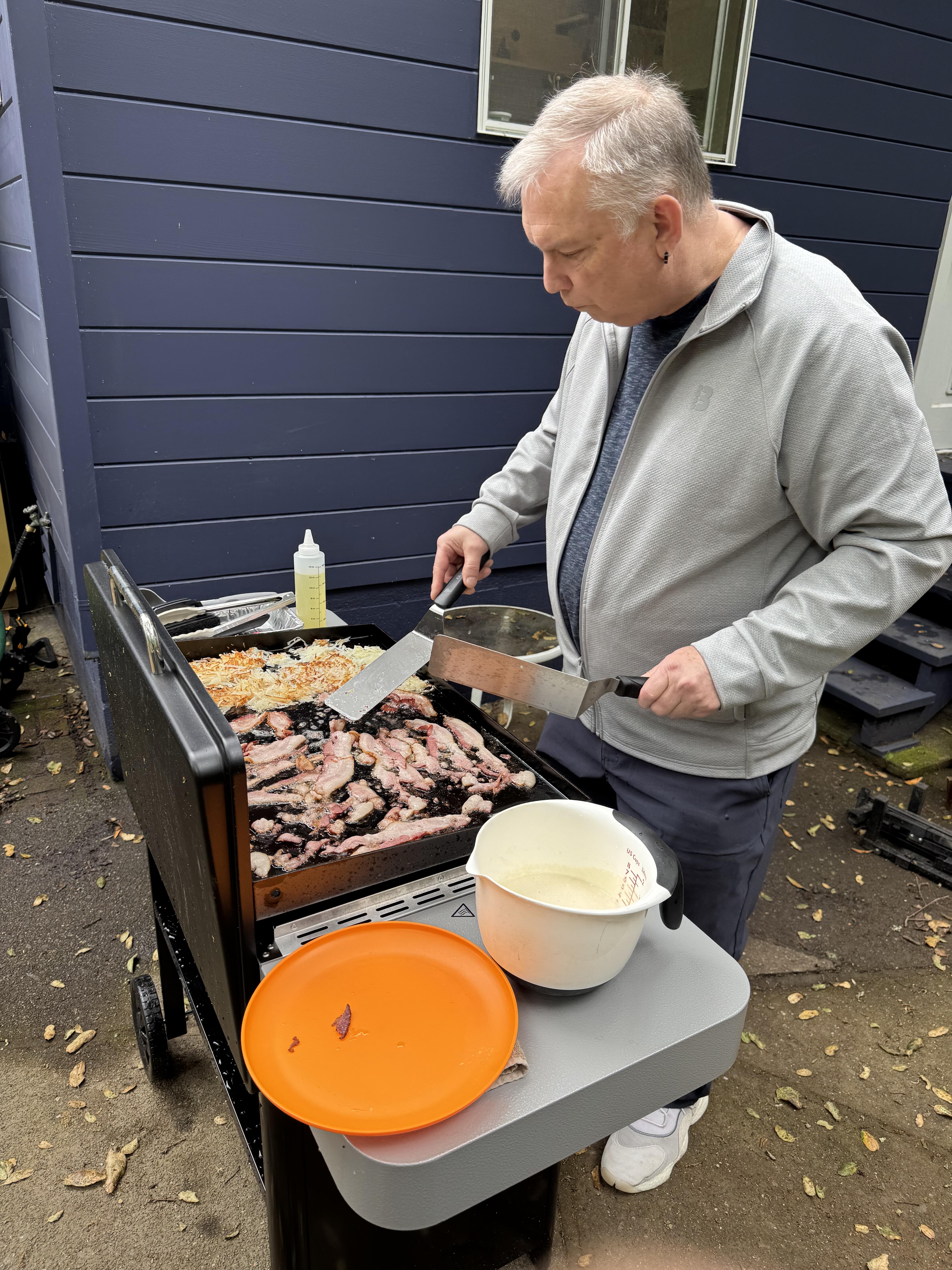
Fried rice on the flat top is a game changer. And yes, temps can go very high. Just watch out for the sensitivity to ambient temps and wind. They are a lot more affected by that than a regular grill, in my brief experience. I had one very cold morning where pancakes almost couldn’t be cooked.
- Last week
-
Almost finished. A classic for a reason.
-
You might say I follow the strategy of DIY T2 PSU by Kevin. I have two PSU I’m using for all my electrostatic amplifiers. One original T2 PSU and one I made myself basically same as the original but with KGSSHV PSU regulators. Bottom line: I’ve never have bother about grounding strategies. So far, I haven’t had any issues with ground loops that I’m aware of.
-
1Q84 by Haruki Marukami Fun and extremely long...
-
the neutrik jacks i used in the diy t2 are actually 4 wires. the connector shell is a seperate wire. i put in a jumper to chassis ground for that wire.
-
Correct me if I am wrong. The Ground Pin(Pin1) has been connected to the XLR socket shell by default by the manufacturer in some cases. This way, the ground pin should be left unconnected to avoid a looping ground. In this case, the loop may be like this: XLR(Pin 3)-> AMP signal ground - > L bracket - > chassis -> XLR(Pin 3). I just realised the L-bracket is isolated to the signal ground, so it should be fine.🤐 I assumed the amp chassis ground wires are connected to the PSU chassis somewhere, and the amp signal grounds are merged with the XLR ground, and then connected to the PSU power supply ground somewhere.
-
Two wins.
-
With Outkast keeping Oasis out of the RnRHOF, there really was only one choice tonight.
-
 haearn joined the community
 -
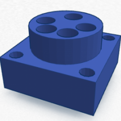
I like the idea about to-252. First draft… …have to think about this. XLR ground pin to signal ground on PCB.
-
Steve's double spatula game was intense!
-
Didn't take pics, but cooked bacon, hashbrowns and pancakes on the new griddle. Dorothy cooked scrambled eggs inside. Worked fantastic! My assistant griddler (DOTU)) and I made quick work of it, and had fun.
-
IXTP10M90S can be replaced with IXCP10M90S(TO-252). If KSC2690 can be replaced by something else with an SMD package, we can eliminate all the aluminum oxide isolations. BTW, what is your grounding strategy? Seems like the ground pins of the XLR input go back to the PSU enclosure.


.jpg.ef79c55e048ca5b492f28b8c9b0a3d4f.jpg)